Hi,
My JVC amp broke years ago and I got the repair-manual from JVC. Damn handy in taking the amp apart...
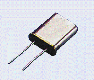
It won't start up 9 out of 10 times. When measuring, I found that it will start up consistently whenever I put my oscilloscope probe on the 'resonator', the cristal-type thing near the processor. Hence I concluded this part is broken.
I considered putting a 1Mohm resistor between it's legs and ground and may try this if I can't get a replacement part (3$ + 40$ shipment )
)
But I'd thought I'd ask you guys/girls first for advice. So you have any?
btw: the partnumber is ECX0004-194KM
My JVC amp broke years ago and I got the repair-manual from JVC. Damn handy in taking the amp apart...
It won't start up 9 out of 10 times. When measuring, I found that it will start up consistently whenever I put my oscilloscope probe on the 'resonator', the cristal-type thing near the processor. Hence I concluded this part is broken.
I considered putting a 1Mohm resistor between it's legs and ground and may try this if I can't get a replacement part (3$ + 40$ shipment
)But I'd thought I'd ask you guys/girls first for advice. So you have any?
btw: the partnumber is ECX0004-194KM
An externally hosted image should be here but it was not working when we last tested it.
An externally hosted image should be here but it was not working when we last tested it.
An externally hosted image should be here but it was not working when we last tested it.
An externally hosted image should be here but it was not working when we last tested it.
It's just a 4.19MHz ceramic resonator. Any 2-pin resonator with this spec will do.
CERAMIC RESONATOR 4.19 MHZ - ZTA-4.19MG
If they're using a resonator i doubt it has to be exact. A 4.194304MHz crystal would probably also work.
CERAMIC RESONATOR 4.19 MHZ - ZTA-4.19MG
If they're using a resonator i doubt it has to be exact. A 4.194304MHz crystal would probably also work.
Strange problem.
It may well be a duff resonator or it could be that the "shock" of stabbing it with a probe causes the oscillator to start.
Only easy way to know for sure is to replace the resonator to eliminate it. Check for dry joints too... maybe it's the physical pressure of the probe doing something. Check the basics if the oscillator is stopped... confirm supplies and that the reset pin is correct and that grounds are good.
For no good reason you could try turning the resonator around
After posting I checked the processor specs and found it to often work with 4.19MHz crystals.
But do I need 4.190, 4.19152, 4.194304 ? Does it need a specific frequency for handling the digital inputsignals and does this resonator have to be very tightly specc'd? Those were questions I was pondering about, but from the above I gather it's not that important. Thanks, I'll just try to get one like in the link.
BTW, iirc it is drawn in the schematic without a groundconnection, but in reality it IS grounded. How do I go about handling this? Would the linked resonator still work?
That was my reason for wanting to add >1Mohm resistors to it
But do I need 4.190, 4.19152, 4.194304 ? Does it need a specific frequency for handling the digital inputsignals and does this resonator have to be very tightly specc'd? Those were questions I was pondering about, but from the above I gather it's not that important. Thanks, I'll just try to get one like in the link.
BTW, iirc it is drawn in the schematic without a groundconnection, but in reality it IS grounded. How do I go about handling this? Would the linked resonator still work?
Consider that the oscillator works with the (likely) extra capacitance of the probe. Why not simply add a small cap. of say, 5-10 pF to ground, as discrete circuits use with the same resonators or crystals?
That was my reason for wanting to add >1Mohm resistors to it
The exact frequency may or may not be vital. It will almost certainly be tied into things like the remote control and so on but anything like that and most things system control related have a very wide margin.
(Generally though ...it becomes vital when it's a master clock used for some specific process that has to run at the correct speed. Fit a slightly incorrect crystal in CD player and it will all work but all run either fast or slow. Similarly it's important if it's used in something that will connect to other equipment on the same standards such as an ADC to DAC and so on. Ceramic resonators are far less accurate than crystals and would never normally be used for anything like that).
What do you mean by "grounded" ? If you mean one lead is grounded then that's no problem. The resonator still goes in either way, it doesn't matter.
In early micros for displays and controls (eg Siliconix types) the crystal was fitted and both ends shunted to ground with small caps externally. These days, it's done inside the chip and so the parts count is reduced.
We have to be careful with digital and signal ground but might I suggest that adjacent "G" pins 18 & 19 could be suitable. I would add that there have been random issues with insufficient capacitance on some chips supplied locally over many years for various display and 'micro' kits and this starting problem still randomly occurs even on some PIC micros.
All the same, this doesn't detract from what Mooly & Jaycee have said from a service POV as the resonator itself could simply have deteriorated since manufacture.
Last edited:
Sorry, I have missed some answers...
Thanks Janneman for your offer, but I had already ordered a crystal from Hajé that arrived yesterday.
It is a 4.194304MHz unit, but since this is only 0.1% off and since I ran into resonators with less accuracy in my searches, I'll give it a go. I will save the resonator incase it doesn't work out and refit it with some extra pF's.
I did resolder (but not remove and resolder) the resonator when I first found the error, but this did not solve the issue.
So should I just put this crystal in? Or should I indeed wire in two 5pF's from each leg to the ground that the resonator used to occupy? (The resonator has three pins in a straight line, where the middle one is ground iirc. The schematic does not show this ground, which I found quite odd. It does NOT have external caps iirc) And is 5pF OK or do you advice another value?
Thanks guys!!! (And girls?)
Last edited:
You are just going to have to try it and see what happens.
Ceramic resonators and quartz crystals are very different in their properties and power dissipation and so on.
Make a note of the amplitude of the signal with the original and new. As long as it is similar or higher there shouldn't be a problem. You may well need the caps from each side to ground. Your 3 pin resonator probably includes those.
Most uprocessor clocks are based on something like this,
Attachments

I measured the amplitudes, but they were all over the place. Hopefully due to an ancient oscilloscope Both the resonator and the crystal showed a difference of a factor of 5 in amplitude from time to time for no apparent reason 
Fact is the crystal fit right in and I'm listening to a working amp right now
It's MP3's on my phone through analog jackplug. My CD-player from 1990 is broken, so I have no gizmo with a digital output to test if the amps AD-converter still works too (minute chance the resonator was used in some timing somewhere and the 0.1% difference in frequency could mess things up).
Thanks a million for your advice guys! No clue why I waited 10 years with fixing this amp... Probably because the internet wasn't this evolved a decade ago, so I didn't post this or get this much feedback back then.
God how I love this amp... 18kg (40 pounds) for a measly 2x100W. Maybe nothing to you Krell owners, but hurting my back in schlepping it two floors down brings a smile to my face. And now it is fixed, even more. And it seems to like my recent purchase: same age MB Quart 310 sub and 290 'satellites'.
I saved the resonator.
Both the resonator and the crystal showed a difference of a factor of 5 in amplitude from time to time for no apparent reason Fact is the crystal fit right in and I'm listening to a working amp right now
It's MP3's on my phone through analog jackplug. My CD-player from 1990 is broken, so I have no gizmo with a digital output to test if the amps AD-converter still works too (minute chance the resonator was used in some timing somewhere and the 0.1% difference in frequency could mess things up).
Thanks a million for your advice guys! No clue why I waited 10 years with fixing this amp... Probably because the internet wasn't this evolved a decade ago, so I didn't post this or get this much feedback back then.
God how I love this amp... 18kg (40 pounds) for a measly 2x100W. Maybe nothing to you Krell owners, but hurting my back in schlepping it two floors down brings a smile to my face. And now it is fixed, even more. And it seems to like my recent purchase: same age MB Quart 310 sub and 290 'satellites'.
I saved the resonator.
I doubt the microcontroller clock is used as a clock reference for any DAC in the unit... resonators are not accurate enough for that job...
It was mentioned that a resonator probably wouldn't be used for this, but even if it would, the analog side works!
Oscillation amplitude - were you using a 10:1 probe? If not, the loading of the 'scope was probably enough to mess it up.
A 100:1...
Bloody expensive and once bought for measuring my tube-amps that I never made...My cheapo 1:1's don't have tips anymore, they got lost in the last two house movings...
- Status
- This old topic is closed. If you want to reopen this topic, contact a moderator using the "Report Post" button.
- Home
- Amplifiers
- Solid State
- JVC AX-Z1010 repair, resonator broken? Help?