Has anyone here used these relays before although they don’t cost a buck ") ?
?
https://eu.mouser.com/datasheet/2/657/pf-series-ac-pcb-mount-1370835.pdf
Solid State Relays | Panasonic Industrial Devices
?https://eu.mouser.com/datasheet/2/657/pf-series-ac-pcb-mount-1370835.pdf
Solid State Relays | Panasonic Industrial Devices
SYMEF
Hello Routhun
greetings is it possible to share schematic for symef as built
by you
warm regards
Andrew
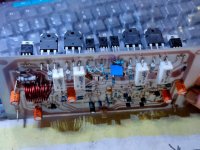
Here is my SYMEF in a case. It is such a beautiful sounding amplifier if you have this one your music comes to life. I'm not a good reviewer, but here are my observations.
This amplifier immerse you in music, and it puts an emphasis on the singer and brings him/her in front of you. One thing I have observe is this amplifier makes the speakers sound the way it wants to. I can tell this for sure, when I switch between different amps, this amp immediately brings its character to the sound. Other amps can't influence the sound that much, more or like dictated by the speakers, but this amp is special.
Thank you Mr. Harrison for the gift. It is kind of life time gift and stays with me forever.
One question Mr. Harrison, I would like to build version 2 PCB but want to operate at +/-50Vdc. Is it possible to run SYMEF at +/-50Vdc? If so what are the changes needed to the schematic? I will have adequate heatsinks for increased dissipation.
Thank you,
Routhun
Hello Routhun
greetings is it possible to share schematic for symef as built
by you
warm regards
Andrew
SYMEF
Hello
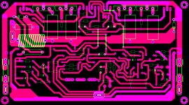
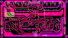
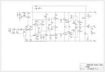
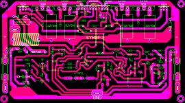
greetings series bulb is glowing full bright there are no shorts on pcb
attached is the schematic and pcb layout i am following maybe some
sharp eyes could help me.
warm regards
Andrew
Hello
greetings series bulb is glowing full bright there are no shorts on pcb
attached is the schematic and pcb layout i am following maybe some
sharp eyes could help me.
warm regards
Andrew
Attachments
Hi Andrew,
Yes the schematic is correct and it is working for me. Two things to try for disconnect the collectors of power transistors and power up using some serial 10 ohm 1/4 watt resistors. By disconnecting the collectors and this 10ohm resistors will help reducing the large currents and enable you check the voltages. With this you can find any issues in wrong components, shorts etc. The emitter voltages at Q2 should be 0.5v and Q16 should be -0.5v. Similarly at Q1 emitter it should be around 1v and Q18 emitter should be -1v. If these voltages are correct, then amplifier might by oscillating, check the miller and feedback capacitors.
Hope this helps. This circuit is stable few people built it and it should work
Thanks,
Routhun
Thanks, your already one of my successesWish you great success with this new revision Mr. Harrison
For more audio related information and fun subscribe to and keep watching these two channels for upcoming SYMEF type S reviews from different perspectives. Other than the upcoming reviews. These channels are also fun.
https://www.youtube.com/@ThomasAndStereo
https://www.youtube.com/@audionautica6843
https://www.youtube.com/@ThomasAndStereo
https://www.youtube.com/@audionautica6843
- Home
- Amplifiers
- Solid State
- SYMEF amplifier