Thanks, Richard.Try a bipolar electro in place of polar-electro. they offer better measurable performance in low thd audio circuits.
Are they better than two low low inductance, high capacitance and low ESR polarized in serial, upside down ?
Are-they better even when, as in SSA, they are working with a DC offset ?
here it is:
Is anyone selling these boards or is it time for me to man up and learn how to etch?
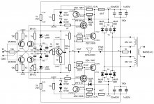
Today i power up the amp, both trimpots are set to maximum resistance
The offset is -1,1v and is settle slowly to -1,55v and swing to -1,59v and it seems i can't bring down more than -1,40v
The BF's heatsink is barely warm
Any sugestions
First look if there's 15 V on zeners. DC offset and VAS/TIS bias is set by changing 2 k trimmer. If that is not successeful than change also opposite 1 k fixed resistor. What's the mid feedback bridge voltage?
Very clever circuit; current driven front end with current feedback....
No. it's voltage feedback.
Oh, please !!!!!No. it's voltage feedback.

No. it's voltage feedback.
Hi Mike

Of course it is:
Uout=(Rf/Rg+1)*Uin=G*Uin
G=Uout/Uin
nothing else but voltages, satisfied.

But if you look to subtraction node you can only find currents make it all happen, in a OLG manner:
Ib+Ic+Ifb+Ignd=0
and because feedback divider directly supplies its part (Ifb) to these currents at subtraction node, we, by its nature, call it Current Feedback Amplifier.
....and because feedback divider directly supplies its part (Ifb) to these currents at subtraction node, we, by its nature, call it Current Feedback Amplifier.
No. It's voltage sampling at the output and voltage subtracting at the input: it's a voltage feedback amplifier.
Between led's and 1k/2w i have approximately 17v, between led's and zenners i have 15v
Should i change 1k resistor with 2k trimpot?
I don't understand exactly, where to measure mid feedback bridge voltage?
OK, it's good that all voltages are marked in sch. Just connect negative test lead of voltmeter to GND and positive to all marked points and you should measure similar voltages as in sch. Mid bridge voltage is difference between +0,645 V and -0,645 V, that means 1,29 V. If all properly done 2 k trimmer is enough to set DC offset to zero and at that point VAS bias current should be around 10 mA. If you cannot set DC offset to both polarities that means something else is not in symmetry. Please first measure all voltage points as instructed and try to find where your SSA's unsymmetry has the roots.

No. It's voltage sampling at the output and voltage subtracting at the input: it's a voltage feedback amplifier.
From the outside point of view, yes, but we people like to call all phenomenons by their true nature, roots, whatever you call it, just to be more specific and to diverse it a direct meaning, to immeadiately know what we are talking about. That is usual and most likely it will always be also in the future, no matter the technology will face.

V=RI, an other question ?No. It's voltage sampling at the output and voltage subtracting at the input: it's a voltage feedback amplifier.
"Current feedback" amplifier is a sort of generic or commercial name given (i believe by AD) to a well known feedback topology which as been explained and described ad nausea, including in this thread.
What are-you trying to do, feed the troll ?
LTP has not bee invented by a tailor neither.
V=RI, an other question ?
"Current feedback" amplifier is a sort of generic or commercial name given (i believe by AD) to a well known feedback topology....
This "well known feedback topology" should never have been called "current feedback" as it was always correctly known as voltage feedback.
Moreover the small signal analysis model used by virtually all IC manufacturers now is entirely incorrect.
I don't like the name "Microsoft", neither, Windows is not a micro software at allThis "well known feedback topology" should never have been called "current feedback"
.
Last edited:
But if you look to subtraction node you can only find currents make it all happen, in a OLG manner:
Ib+Ic+Ifb+Ignd=0
and because feedback divider directly supplies its part (Ifb) to these currents at subtraction node, we, by its nature, call it Current Feedback Amplifier.
But that is a topological difference, not a mathematical one. If you built a CFB and VFB amp with mathematical instrinsics they'd perform exactly the same. One can call it anything they want as long as they know how to rearrange the math so it appears to support their conviction. Calling it "voltage" or "current" feedback is confusing because in pure math there is no difference between voltage and current; the math is perfectly symmetrical. In math we treat one as a consequence of the other but this is a simplifying convention and has nothing to do with reality (chicken or egg). We each choose to think in terms of voltage and current interchangeably at different times, and often equivalent views seem totally different; no one can ever agree about CFB vs VFB because neither is a valid description of the reality.
Reality is what determines the difference between CFB and VFB. A way to describe the difference that in 3 words tells the reader almost everything they need to know is "common-base feedback". It's a lot more descriptive than "current feedback" which confuses math/theory with reality and tries to use them interchangeably. Going by this logic we also have common-emitter feedback (CEF) and common-collector feedback (CCF). This describes all the important differences between VFB/CFB doesn't it?
Like this ?A way to describe the difference that in 3 words tells the reader almost everything they need to know is "common-base feedback".
http://www.angelfire.com/sd/paulkemble/ssm2131pa.gif
(Closely inspired from Mark Alexander ©Analog Device)
The game is to understand how this amp (Current mirror of the OPA's consumption) and SSA both rely on the same so called CFA principles.
Last edited:
- Status
- This old topic is closed. If you want to reopen this topic, contact a moderator using the "Report Post" button.
- Home
- Amplifiers
- Solid State
- Simple Symetrical Amplifier