You might oughta Taylor around that Rush to keep both comparator emitters
current more or less at constant. That way voltage drop won't curve so much...
Its never gonna be constant, or you wouldn't get any error voltage swing at
the collector resistor. But you can approach that ideal.
No, wait... Your JLH IS a Taylor! Holding R10 (and R2 on the right) at two
emitter drops. I just didn't see at first. But then again, those are output
emitters under dynamic conditions for a constant voltage reference...???
Perhaps this makes emitter drops in the Rush to copy a similar dance?
Two emitter drops (in the Rush) may simply double the magnitude of this
non-linearity. Which is really the non-linearity of the output emitters.
Last edited:
Member
Joined 2009
Paid Member
I thought there was perhaps a benefit from having the complimentary emitters back to back like that in terms of distortion cancellation ?
Member
Joined 2009
Paid Member
No, wait... Your JLH IS a Taylor! Holding R10 (and R2 on the right) at two
emitter drops. I just didn't see at first. But then again,
he he he, you will see from the thread I started for my JLH design my claim that All amplifier topologies are separated by '6 degress of freedom' - there are no new circuits left to find, they are all out there. I've started from a dozen different novel places and a few twists later I pop out at one of the other circuits.
Transistors only have 3 terminals, there's only so many ways of putting them together. Over the years we've enshrined all sorts of circuit pieces with names, usually after the person who published it somewhere, but there really aren't that many ways of doing this.
The tunnels and passages that connect all the different topologies together are a lot of fun to explore and I think it's a big part of the hobby for some.
Gareth,
The RC is good, but so is the singleton...... bear with it, it's worth a good look too.
I suspect you need to run your RC at around 1mA minimum, 1.3/8.2mA (160uA) is not enough. I don't believe you need R9 as you are not using the RC as a phase splitter, though the idea does have merit here.
Hope this helps,
Hugh
Try adding 100ohm resistor between emitters of rush cascode, it will help in linearising the response and will provide you with much flater bandwidth and HF response.
then you can "fold" the rush cascode input, changing one Q polarity and get the diff pair which has the even order distortion cancellation, input offset cancellation and high input Z on both inputs all in one
then you can "fold" the rush cascode input, changing one Q polarity and get the diff pair which has the even order distortion cancellation, input offset cancellation and high input Z on both inputs all in one
Have done that a longtime ago using both BJTs and FETs. Works great and gives a good harmonic stucture.
This one is just to find if there is some magic hidden in the Rush.
Two emitter drops (in the Rush) may simply double the magnitude of this
non-linearity.
Higher current helps marginally but THD is still doubled with no better harmonic structure. kenpeter you might be on the right way there!.
Adding 100ohm doubled it one more time.
Will add the LTP version for comparision.
Last edited:
Not exactly... You got Rush + Taylor + JLH.
If Taylor was working with a good reference, it would be holding both emitters
of the Rush at constant working current and voltage. Linearity would be moot.
But your Taylor's voltage ref for comparison and correction of Rush collector
current is the JLH drive, and one output transistor. Not exactly what you call
a steady voltage reference, once the music starts...
This voltage non-linearity is copied to Rush collector current by Taylor circuit.
Then Rush modulates the problem twice over a single emitter. But not its own
fault, I gotta blame abusing output and drive transistors as voltage reference.
Hey Ken,
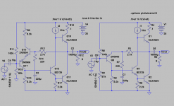
You must show me the Taylor? This as the circuit is exactly a JLH 10W with the added Rush in the input/feedback stage. Note the 0.1ohm is just for monitoring Iq, should maybe be made smaller.
To me a Taylor, simply put, is closely related to a WF with transistor instead of capacitor in the "feedback" from the top of the upper device(mut be a resistor on top of the drain/coollector to generate a signal) driving the gate/base of the lower.
Last edited:
Member
Joined 2009
Paid Member
Revintage, I share your perception of the Taylor. For me, the key feature of a Taylor is that the signals on the emitter and collector of the Taylor device are in-phase - i.e. that for all intents and purposes is operating in what folks like to call Common Base.
Q10 is White. Q12 Taylor. OK, so you got emitters here appear turned backward, but
the functions served are exactly per the classic. I got no better names to describe.
You are holding the voltage drop of R10 to a two emitter drop constant (Q12 + Q11)
Thus the current in the Rush (Q17+Q13) always corrects itself toward this reference.
And if the reference is a stable one, the emitter drops in the Rush won't vary more
than minimum necessary to maintain that relationship. The ugly current swings will
be offloaded to the emitter of Q10.
I'm just sayin Q12 +Q11 is a voltage reference (intentionally or not). Simultaneously
handing drive and output current swings. So its not a stable voltage reference. And
the Taylor circuit therefore isn't holding the Rush to a particularly steady current.
If you can separate the output function from the voltage reference function, then
the Rush will correct itself toward a constant current and a constant voltage drop.
It is confusing when multiple topologies are overlayed upon the same transistors.
Sometimes a synergy of topologies saves parts. Sometimes it just works better.
Definately worth exploring, with caution that the synergy is true, and one function
doesn't mutilate the other.
Last edited:
I just notice the "JLH" current steering emitter is not turned to make a unity
gain half diamond. Its referenced to the lower rail, for open loop voltage gain.
But I've seen this before, and was nagging the back of my mind, what was it?
Yesterday I gave a class on 7400 logic, and had my students (at work, not
teaching at real school) build a DTL NAND gate from 2n2222's and discretes.
It hit me, the output stage topolgy was identical! This output is TTL!
Same like JLH, quiescent current is less at either extreme than in the middle.
It makes sense for Logic gates that won't spend too much time inbetween,
or want to move fast through the transition.
Wonder how this compares to 7404 inverter with negative feedback?
I think your Taylor input buffer might still have the edge.
Last edited:
- Status
- Not open for further replies.
- Home
- Amplifiers
- Solid State
- Rush Cascode inputstage on JLH 10W