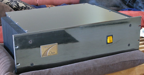
Need some help here. I have a amp I bought a while ago off a friend of a friend who built it. It's been sitting in my storage for years collecting dust and debating whether it's worth modding out or try to sell it. It currently sounds ok but no where near as nice as my Ayre AX-7e.
Does it have good bones, parts, design ??? Is worth investing in or dump it for something else to play with?
What kind of design is it?
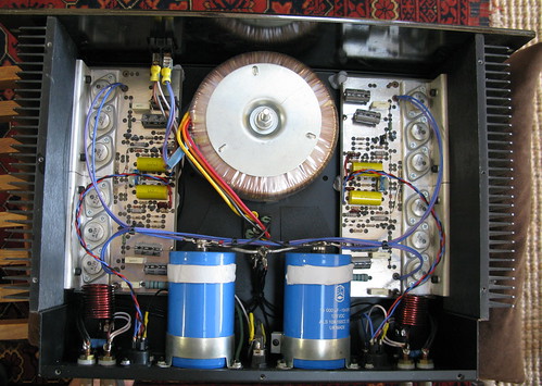
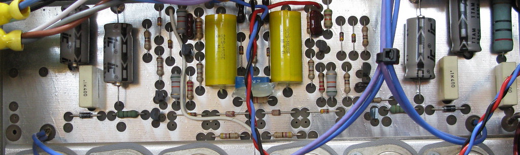
It's suppose to have 100wpc @ 8 Ohms. The binding post are Cardas CCBP, the yellow caps are Muse, BHC (UK), speaker wire I think is Kimber PBJ. Balanced inputs.
Thanks for any advice!
Click for large size:http://farm3.static.flickr.com/2570/3972367143_1df10f6b83_b.jpg
Click for larger size:http://farm3.static.flickr.com/2668/3973139034_71c0acb470_b.jpg
Click for large size:http://farm3.static.flickr.com/2620/3972374699_d5ef08ff92_b.jpg
Click for large size:http://farm3.static.flickr.com/2460/3973147264_60f5d3c032_b.jpg
Does it have good bones, parts, design ??? Is worth investing in or dump it for something else to play with?
What kind of design is it?
It's suppose to have 100wpc @ 8 Ohms. The binding post are Cardas CCBP, the yellow caps are Muse, BHC (UK), speaker wire I think is Kimber PBJ. Balanced inputs.
Thanks for any advice!
Click for large size:http://farm3.static.flickr.com/2570/3972367143_1df10f6b83_b.jpg
Click for larger size:http://farm3.static.flickr.com/2668/3973139034_71c0acb470_b.jpg
Click for large size:http://farm3.static.flickr.com/2620/3972374699_d5ef08ff92_b.jpg
Click for large size:http://farm3.static.flickr.com/2460/3973147264_60f5d3c032_b.jpg
Last edited:
Hi mr_macgee!
It look likes like My Perreaux PMF 1850, but.........???
Regards zeoN_Rider
It look likes like My Perreaux PMF 1850, but.........???
An externally hosted image should be here but it was not working when we last tested it.
An externally hosted image should be here but it was not working when we last tested it.
An externally hosted image should be here but it was not working when we last tested it.
Regards zeoN_Rider
Looks nice
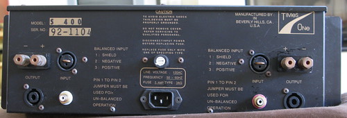
Hmm, coould have been diy, but back panel looks professional
Ehh, I dont see any other transistors than the output ones
Might make a nice woofer amp
Balanced in is not very common
Even rare is the Speakon output connectors
If you need to ask, dont try and mod it
The only mod I would try would be to mount better amp boards
It cost money, but might be worth it
What you have, like box, supply, connectors, all cost serious money
Last edited:
Ehh, I dont see any other transistors than the output ones
Look better, or use glasses
")
An externally hosted image should be here but it was not working when we last tested it.
Regards zeoN_Rider
Looks nice
Hmm, coould have been diy, but back panel looks professional
Thanks,
The person who built it was trying to build start up business in Audio. One of his first clients was Sony Recording Studios, he made a bunch of them for them and needed to make the cases as professional looking as possible. He stopped making amps a little after I bought one. I don't think many other amps have been built in Beverly Hills.
I think I would have a hard time selling it so I thought maybe I should play with it. Your right, I'm not an old hat at building amps but would like to learn, hence the questions to this forum.
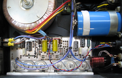
To make it easier to see, click here for large detailed close up:http://farm3.static.flickr.com/2524/3972522931_c3de4766f7_o.jpg
http://farm3.static.flickr.com/2543/3973328306_aed0c85634_o.jpg
An externally hosted image should be here but it was not working when we last tested it.
Let me know if there are other pics needed to get a better idea of the amp.
Again, thanks for your help and info!
Last edited:
mr_macgee
it`s very likely a good sounding amp, well-built, maybe you should leave it as is.
it`s very likely a good sounding amp, well-built, maybe you should leave it as is.
A bad idea.Might make a nice woofer amp
Let me know if get a better idea of the amp.
Again, thanks for your help and info!
Don't touch anything.
Sell Me!

Regards zeoN_Rider
Don't touch anything.
Sell Me!
Regards zeoN_Rider
I'm not married to this amp. I'd be happy to sell it.
I'm not married to this amp. I'd be happy to sell it.
I should say I'm not married to this amp but I would still like to know more about this type of amp design and build quality.
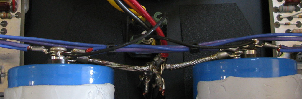
I'm trying to learn more about the amp. Is there anything that can be improved? Why are there so many conductors going to each binding post? Would it benefit bypassing the speakon connectors? Why would you need to use a jumper in the balanced input to use the un-balanced inputs? Sorry for the silly question.
Cheers
PS: So far the response is "don't touch it" and it's a nice build. I would also be up to trading it for someone's DIY amp to try something different. You can always PM me.
PS: So far the response is "don't touch it"
Don't you think you should start out at the bottom and work your way up ?
Learn how amps work in general, then learn about different topologies, and finally when you know all about amps, then you try to improve this one ?
The 2SJ50 and 2SK135 are nice devices, they should make the basis for a great amp. The other (expensive!) stuff like the power supply, housing and cooling also look more than adequate to me.
Of course, I don't know of any circuit details, but one thing struck me as odd. I see only small (TO92 or something similar) signal transistors besides the power MOSFETs. This seems to indicate that three paralleled MOSFETS plus their complementaries = 6 pcs together, with a high input capacitance that is not constant, are driven by a puny little driver stage. That might explain why you don't find the sound of it to be exactly stellar.
If you look at ESP's project 101, http://sound.westhost.com/project101.htm , you'll see that he uses a bigger driver transistor than the ones found in your amp. You could use this design, substitute the output transistors Rod uses with the ones you have (they're drop-in substitutes for each other, only the case is different), and see if things improve. Given that you already have all the expensive components, this endeavor shouldn't be too expensive. If you don't feel competent, it might make an interesting project for someone else.
Hi Timpert
Hi Timpert,
Thanks for taking the time and your input, I appreciate it. I'll study up on what you mentioned and figure out how to proceed next. I definitely need to learn quite a bit more. This amp has been motivating me to do that.
I've had this amp in several different rigs, it can sound quite nice but it's also missing speed, dynamics and the bass is not as well defined or tight as it should be compared to my Ayre, even my Classe CAP-151 has an slight edge on it but not by much.
I feel that this amp is missing something and perhaps with a little work it can be improved, by me or more likely someone else. It's the one reason I have kept it, I watched him build it and I was sure it had good bones. It's nice that others think the same. It would be a shame to discard it/sold off cheaply.
Any idea of what sort of design that this amp is based on?
Cheers
The 2SJ50 and 2SK135 are nice devices, they should make the basis for a great amp. The other (expensive!) stuff like the power supply, housing and cooling also look more than adequate to me.
Of course, I don't know of any circuit details, but one thing struck me as odd. I see only small (TO92 or something similar) signal transistors besides the power MOSFETs. This seems to indicate that three paralleled MOSFETS plus their complementaries = 6 pcs together, with a high input capacitance that is not constant, are driven by a puny little driver stage. That might explain why you don't find the sound of it to be exactly stellar.
If you look at ESP's project 101, http://sound.westhost.com/project101.htm , you'll see that he uses a bigger driver transistor than the ones found in your amp. You could use this design, substitute the output transistors Rod uses with the ones you have (they're drop-in substitutes for each other, only the case is different), and see if things improve. Given that you already have all the expensive components, this endeavor shouldn't be too expensive. If you don't feel competent, it might make an interesting project for someone else.
Hi Timpert,
Thanks for taking the time and your input, I appreciate it. I'll study up on what you mentioned and figure out how to proceed next. I definitely need to learn quite a bit more. This amp has been motivating me to do that.
I've had this amp in several different rigs, it can sound quite nice but it's also missing speed, dynamics and the bass is not as well defined or tight as it should be compared to my Ayre, even my Classe CAP-151 has an slight edge on it but not by much.
I feel that this amp is missing something and perhaps with a little work it can be improved, by me or more likely someone else. It's the one reason I have kept it, I watched him build it and I was sure it had good bones. It's nice that others think the same. It would be a shame to discard it/sold off cheaply.
Any idea of what sort of design that this amp is based on?
Cheers
Last edited:
Any idea of what sort of design that this amp is based on?
I have no idea. But you could take out one PCB and look at the underside. The circuit doesn't seem very complicated, so reverse engineering it might be a good start. Be sure to note the transistor type numbers and google for their datasheets, because different small signal transistors can have different pinouts even in identical looking packages.
Any idea of what sort of design that this amp is based on?
Cheers
It similar to Crescendo or David White"s Mos Fet Power Amp.
Or old Hitachi.
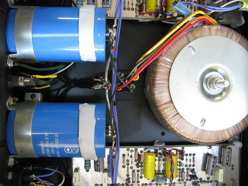
Put some larger main capacitors!
Regards zeoN_Rider
This amp has potential as many of the components are of good quality.
I would guess, as others have stated, that this is yet another Hitachi Application Notes clone.
I quickly searched around the net and found a typical circuit diagram here:-
http://www.plexoft.com/SBF/mounted/0tube.html
Where this circuit becomes unstuck is when the number of output mosfets is increased. The capacitive load of the mosfet gates are too much for the amplifier circuit to drive properly, without adding an extra driver stage.
You would need to be able to sketch out the circuit to reverse engineer it.
I usually remove the PCB, and use a lamp to illuminate the board to see through both sides at once. But I see this PCB has an extensive ground plane on the top side!
The other technique I use is a pencil and a rubber to sketch out what I find.
If you can discover what transistors are used, this will help you figure out the schematic.
Hint A lot of transistors are labelled without the 2s at the front.
ie a1085 is 2sa1085.
If this is seems to much for you, then maybe you should leave alone.
Hi!
Don't break your brains!
It's all the same!
Below is the schematic of Perreaux Amp.
Compare!
Regards zeoN_Rider
Don't break your brains!
It's all the same!
Below is the schematic of Perreaux Amp.
An externally hosted image should be here but it was not working when we last tested it.
Compare!
Regards zeoN_Rider
I think the easiest tweek would be to soup up the driver stage: replace the TO92 thingies with something a bit heftier (with some leg bending you could even re-use the PCB you have now), Rod Elliot uses the MJE350. You also need it's NPN complement, the MJE340. In Zeon's schematic, the stage consisting of Q3,4 and 5 is of concern. Replace Q3 and 4 with the MJE340 and Q5 with the MJE350. Then increase the operating current of the stage by about a factor of two, by dividing the values of R9, 11 and 12 by two (find the nearest E24 value, then R11 and 12 become 47 Ohms and R9 becomes 130 Ohms). Leave R10 alone. Replace RV1 by a 470 Ohms trimmer and re-adjust the bias to about 300 mA. This is the current the amplifier draws when there's no signal and no load present. If the new driver transistors get a bit too hot for comfort, you can slide a small cooling plate onto them. Of course, general building tips apply like using a light bulb tester or safety resistors. Ample info can be found on this forum.
A lot of earlier MOSFET amplifier schematics show the same flaw: because the output transistors aren't supposed to require any drive current as opposed to a BJT output stage (true, but ONLY for DC), the driver stage is often underpowered. The input capacitance of MOSFETs is rather large, so at higher frequencies the output stage still needs a considerable drive current. The driver is pushed to the limit to deliver this, and that is something you'll definitely hear.
Good luck!
- Status
- This old topic is closed. If you want to reopen this topic, contact a moderator using the "Report Post" button.
- Home
- Amplifiers
- Solid State
- Is this amp worth improving ???