Tino96,
In the first link, Anthony Holton wrote in conclusion :
Please don’t attempt to use any IRFP240 or IRFP9240 devices in this design, It simply won’t work and you will blow up the output stage in seconds after turn on. This design is only suitable for Lateral type Power MOSFET’s
Regards, Pierre Lacombe.
x mik:
the link http://web.tiscali.it/audiofanatic3/Tipo/Stato_solido/pic_finaliSS/120W_MOS_IRF9540_540.jpg
dont't work;
do you have the image?
many tnx
the link http://web.tiscali.it/audiofanatic3/Tipo/Stato_solido/pic_finaliSS/120W_MOS_IRF9540_540.jpg
dont't work;
do you have the image?
many tnx


hi mik, many tnx for all,
my mail: tino96REMOVENOSPAM@inwind.it
REMOVENOSPAM for replay
I add schematic for all
bye
mik said:and you will need this also...
I have whole PDF article which is for IGBT amplifier but everything
is completely the same except values of few resistors, but just look at the schematics.If you want just i'll send you.
Main switch on delay
my mail: tino96REMOVENOSPAM@inwind.it
REMOVENOSPAM for replay
I add schematic for all
bye
JasonL,
I have to agree that Holton's support is poor. The designs are good, but not a good choice for newbies - the PCBs are not too well-made (pads and traces come off so easily) and you can't expect replies to your questions. Hopefully Mr. Holton will return and continue to support the DIY community.
I have to agree that Holton's support is poor. The designs are good, but not a good choice for newbies - the PCBs are not too well-made (pads and traces come off so easily) and you can't expect replies to your questions. Hopefully Mr. Holton will return and continue to support the DIY community.
Banned
Joined 2002
tino96 said:hi mik, many tnx for all,
my mail: tino96REMOVENOSPAM@inwind.it
REMOVENOSPAM for replay
I add schematic for all
bye
can you email it to me too
jleaman@citytel.net
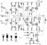
identical schematic supply and pcb
http://users.otenet.gr/~athsam/power_amplifier_65w_hexfet_eng.htm
(good site)
http://users.otenet.gr/~athsam/power_amplifier_65w_hexfet_eng.htm
(good site)
Christer said:but the general answer
would be no, you can probably not use them. Lateral MOSFETs
start to have a negative temp. coefficient already at rather
small Id, so usually no temp. compensation of the bias is
necessary, and indeed Holton's amp follows this practice.
Although I don't know about the IRF240/9240, most, if not
all, non-lateral MOSFETs have a positive temp. coefficient up
to quite high values of Id, several Ampéres, so I would think
they need temp. compensation of the bias.
I thought all mosfet have negative temp coefficient, but i could be wrong there.
anyway, the irfp240/9240 twin does have negative temp coefficient throughout its operating range, if i read the chart correctly. the normalized resistance (Rds) goes progressively higher as die temperature goes up - granted, it doesn't seem to go up as fast as those hitachi lateral mosfets. But the important thing is that it goes up progressively and consistently. so there is no temperature at which the coefficient is positive.
i don't know if that would indicate no thermal runoff but the risk is limited. from personal experience, I have built a few mosfet amps using IRF540/9540 (they are cheap) in place of lateral mosfets with just v-i limiters and I would short the speaker terminals and those devices would survive. I was too chicken to do that without the v-i limiter but I suppose with sufficient amount of ops devices, it is OK.
While I can't say that thermal runaway is not a problem, the solution to it isn't that complicated: add a bias generator. The middle circled BD transistor (indicating mounting on the heat sink) and its associated pot, resistors and such should work for most situations. I've experimented with a similar setup on an OPS with Hitachi FETs (Lateral FETs but at 11amps). I actually like the setup as opposed to the one in the Holton amp without bias generator, as this BG also alows you to set the biasing point for the OPS thus making sure that X-over distortion is minimized (as well as adjustment of bias for different devices. Laterals, Verticles, and BJTs all have differing bias points). I've also read that using another FET instead of the BJT *Might* be a good idea as this will track more like the OPS FETs. This I havn't yet tryed. I've also speculated that adding a bias generator the the Holton Scaleable Amp would meake the amp work with many more OPSes including IRF device. IV limiters would also be a good inclusion.
-Dozuki
Do a search on 'lateral mosfet' a lot of this info is buried here.
-Dozuki
Do a search on 'lateral mosfet' a lot of this info is buried here.
Aside from protecting the amp from thermal runaway the 'amplified diode' approach also keeps the OPS bias set properly throughout the operating temperature. Because the transistor in the BG is attached to the heat sink of the OPS as close as possible to one the output transitors it will change the bias as the temp goes up or down depending on usage of the amp. This will help to keep x-over distortion in check with temp. fluctuation as well.
It's not really all that difficult to incorporate and might save some headach in the long run.
-Dozuki
It's not really all that difficult to incorporate and might save some headach in the long run.
-Dozuki
Hint...
Hint, try the bias generator with about 3 volts of constant voltage drop (3.3V zener, or series diodes not attached to the heatsink), in series with the bias generator transistor. In my experience, that's about what you need to properly bias the 240/9240 devices. (The gain of the bias generator is greater than it needs to be to thermally compensate for the devices... ...long story short, the bias still won't be stable with temperature (Even though the amp won't thermally run away).
-Dan
- Status
- This old topic is closed. If you want to reopen this topic, contact a moderator using the "Report Post" button.
- Home
- Amplifiers
- Solid State
- 200 Watt Lateral Mosfet Amplifier and irfp240/9240