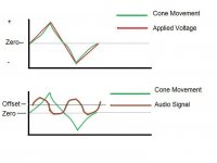
Hi, this has puzzled me for some time, wonder if anyone has any thoughts. I am thinking particularly at very low amplitudes around the zero crossing point of the audio waveform. I hope the drawing makes what I am trying to say a bit clearer. Any D.C. offset will not effect the linearity of the electronics but if the speaker cone is moved from its "rest" position by the offset, is the cone movement still linear when a small A.C. signal is then superimposed on to it. The movement of the cone caused by the offset may be small, and due to the crossover network will effect only the bass and midrange drive units, the tweeter being A.C. coupled. Anyone any thoughts ?
Karl
Karl
Attachments
Last edited:
If the driver is linear over the range of excursion needed by both the offset and signal, there shouldn't be any problem. If the offset pushes the cone into some non-linear region, that's bad, but hopefully that's nowhere near small signal conditions. I believe all drivers compress with increasing amplitude, so you're thinking the right direction, it just comes down to how much offset, how much signal, and what driver. I don't like much of any offset, just because there's no reason to have it in a good design.
Very good point, Karl.
Drivers may have issues with a non-ideal VC resting position, according to information from Klippel (http://www.klippel.de/pubs/papers.asp)
From that it might easily happen that a DC offset from the amp might push the driver in either a more linear area or less linear area, from a small signal view.
I have measured the T/S-Parameters of guitar speakers and experimented with constant current offsets, which showed a big change in T/S-paramters. Initially I started to investigate these things when I found that I couldn't reliably measure the impedance plot of a specific driver, I got two distinct sets of repetable responses, which where introduced by a small offset of the test amp I used and I didn't take care of the polarity in which I hooked the driver to the amp. Took me quite a while to figure that out.
Again, all this is confirmed in the Klippel tech papers. How much of it is really an issue in a good quality 3-way speaker (where only the woofer will be affected)? I don't know...
- Klaus
Conrad and Klaus, thanks for your input on this, the big question of course is "IF" the movement is linear. I know how incredibly sensitive our hearing must be, in order to be able to identify differences in performance of equipment/components etc. Imagine how small the cone movement must be if the voice coil is driven with only a few millivolts of signal, yet it is clearly audible. Is it the "quality" or characteristics of the waveform (as it is reproduced by the speaker) at these low levels that goes a long way to determine how a piece of equipment will perform. I wonder how the harmonic stucture would be altered by any mechanical non-linearity. Untill fairly recently offsets of up to 100mv were not unheard of in comercial equipment (a huge amount really). Thanks for the link Klaus, theres a lot of reading to do here. Your testing methods using Thiele/Small parameters are beyond my abilities but I remember doing an impedance plot using a method I read about. A signal generator (low z out) feeds the speaker through a fixed resistor, think it was 600ohms. By adjusting the generator output accordingly you could read off on a D.V.M. (true R.M.S.) across the speaker it's impedance for e.g. 80mv would be 8 ohm. I must get the calculator out and try this again, my current speakers have a 3 ohm minima. My generator has an adjustable offset, wonder whether this would show up on this test, or would the effect be to small to measure. Thanks again for a bit of lively debate.
Regards Karl
Regards Karl
the effect you are describing is real and I think the answer to your question is yes, a DC offset causes distortion. How much and how audible is another matter. But the principal is correct, the DC offset causes the cone to be displaced from its normal rest location. AC signals do not remove the offset, it persists in the presence of the audio signal. I think the best response is to find an amp with very small offset, mV, if possible or adjust for low offset.
Ted
Ted
I guess the ultimate "test" is to introduce an offset and do some critical listening. As mentioned earlier about impedance curves, it is 600 ohm fed by 6 volts R.M.S. in series with the speaker. Read off in millivolts is proportional to impedance e.g 80mv equals 8 ohm. Credit for this simple method goes to Doug Self, but it is easy and revealing to do.
Karl
Karl
Piano waveforms are known to exhibit as much as 12dB of asymetry, a few millivolts of DC off-set will not be noticed (unless your speaker has an x-max of 0).
The ESP site has examples of tone bursts of asymetrical signals that show what seems to be several volts of off-set when run through a typical amplifier.
This can be a problem with PA, and destroy woofers.
Crown has a circuit called a loudspeaker off-set integrator to reduce this on their vz5000 amplifier.
Depends on a no of things !One being the type of enclosure that is used for the spk. A small infinite baffle (acoustic suspension ) can be asymetric ie a regards cone loading
Maybe if the offset was in the correct direction it might reduce distortion ?
All though I feel that if the amp has more than 50 mv offset then you have problems with the amp any way in this day and age it should be around 5-10 mv no more !
regards Trev
Maybe if the offset was in the correct direction it might reduce distortion ?
All though I feel that if the amp has more than 50 mv offset then you have problems with the amp any way in this day and age it should be around 5-10 mv no more !
regards Trev
One should note that this way of measuring an impedance plot does not yield the impedance that will be seen by an amp. It is a (quasi-)constant-current measurement, while an amp will provide a constant voltage. The VC sees a short circuit, while with current drive it's run open circuit. This affects damping (Qes falls out of the picture without electrical damping, so Qts will simplify to the mechanical Qms). Hence, in current mode, the peak at resonance will be much higher than would be with a real amp's drive conditions.Mooly said:I guess the ultimate "test" is to introduce an offset and do some critical listening. As mentioned earlier about impedance curves, it is 600 ohm fed by 6 volts R.M.S. in series with the speaker. Read off in millivolts is proportional to impedance e.g 80mv equals 8 ohm. Credit for this simple method goes to Doug Self, but it is easy and revealing to do.
Karl
- Klaus
In my opinion, the speaker diaphragm is at mechanical rest and move from this point forward and backward. If for some reason there was another mechanical quantity causing an off set in one direction but happens to be related to a standing fixed voltage, the diaphragm will start movement from this new rest point as if it was the old rest point the same way as it did without the additional bias and nothing will be different. When one reaches to extremety of excurcion then the one direction may be at its mechanical end due to the bias while the other is still far from it and you will find rapid distortion increase due to cone breakup. The distortion is asymmetrical and higher order artifacts will rapidly be encountered.
My 2 cents
This is what I think about it.
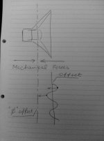
As soon as magnetic field starts moving the cone to either direction from the neutral position, it works against the mechanical "spring" type of force. This force may be considered linear in certain range of cone positions.
However, even considering it linear, as soon as you look at the picture with certain DC offset, you will see that half-wave magnetic field still works against the mechanical resistance, the other half-wave it is supplemented by its force, pushing in the same direction.
At low offsets it is negligible, but the effect is the stronger, the higher DC offset is, resulting in distortion increasing accordingly.
By the way, the lower amp output impedance is, the lower the effect is, as the low impedance output will control the cone tighter, reducing the influence of asymmetric mechanical resistance.
This is what I think about it.
As soon as magnetic field starts moving the cone to either direction from the neutral position, it works against the mechanical "spring" type of force. This force may be considered linear in certain range of cone positions.
However, even considering it linear, as soon as you look at the picture with certain DC offset, you will see that half-wave magnetic field still works against the mechanical resistance, the other half-wave it is supplemented by its force, pushing in the same direction.
At low offsets it is negligible, but the effect is the stronger, the higher DC offset is, resulting in distortion increasing accordingly.
By the way, the lower amp output impedance is, the lower the effect is, as the low impedance output will control the cone tighter, reducing the influence of asymmetric mechanical resistance.
Attachments
- Status
- This old topic is closed. If you want to reopen this topic, contact a moderator using the "Report Post" button.
- Home
- Amplifiers
- Solid State
- Can D.C. Offset cause non linear distortion