Loudspeaker Protector
Post 3/3..... my layout...
I've "compressed" the component density in the layout by about 15% overall, added a 3VA toriod and have inserted 6 and 4 pin headers for connection to LEDs, Channels In and Relay connection.
The device, in it's original PCB setup had options to be powered off the amplifier +ve DC rail (still needed the AC secondaries connected for on/off detect) or it could be powered by a seperate small transformer (as I have done here)..... never liked hanging other circuits off one side of the DC rails so I usually used a seperate transformer.
Have not made this board as yet as I still need to do a final check of correctness.
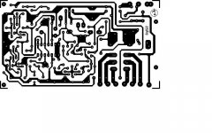
Attachments
UPC1237
Felixx ... thanks for mentioning the UPC1237.... had not come across that one.... very neat.
I'll see if I can get some and test them out.... looks like I may be in for a redesign 🙂
Felixx ... thanks for mentioning the UPC1237.... had not come across that one.... very neat.
I'll see if I can get some and test them out.... looks like I may be in for a redesign 🙂
UPC1237
I looked for the UPC1237.
No-one in Australia seems to carry them that I could find.
Mouser do have a NTE7100 which is the same part (no suppliers have that item in Aust either).
Very expensive to buy a handful from Mouser (they only ship via Fedex or UPS)
I've send an email to the local NTE distributor ... will wait to see what they say.
Best Regards
UPC1237
OK, to get the UPC1237 or NTE7100 will cost me more per device than the cost of building the old cct I ave been using.... not worth the exercise. I cannot see any real advantage in the UPC1237/NTE7100 functionally anyway (other than board size, and that is not an issue anyway).
I will continue to use the original cct.... I know it works extremely well.
Hi! In Doug Self's Book 'Self on Audio' there is a chapter on relay muting with circuits that work very well for pre and power amps. There are also details of a soft start on a web site called 'whitenoise.co.uk', this is a commercial site but the description of the soft start unit will provide a way to go.
'Only when the last animal, the last fish and the last bird are dead will we realise you can't eat money'
'Only when the last animal, the last fish and the last bird are dead will we realise you can't eat money'
Speaker Protector
OK, I've had a rethink.....
The UPC1237 or NTE7100 are out for me but I had been looking around at Protector and Softstart for a while and had accummulated info on various circuits.
Have decided to do a PIC controlled version... should be able to use (e.g.) a 12F675 or similar 8 pin micro... a proper DIY project.
I've developed a range of stuff over the years using PICs and cannot see this being very complicated at all.
The last audio related PIC project I did was a decoder for my Arcam remote in my DIY preamp. The Arcam remote had Vol+, Vol- and Mute buttons and I decoded these to run the motorised pot and mute cct in my pre-amp.
I'll post the final version once done.
and how long will the pic take to work out that the amp is safe to produce music.
My Cyrus delays about 6 seconds for the third relay to click before finalling bringing up the volume to the last setting.
I find these delays annoying.
My Cyrus delays about 6 seconds for the third relay to click before finalling bringing up the volume to the last setting.
I find these delays annoying.
Hi again,
Some duff infor in my last post- whitensoise audio has stopped trading bur the web site is still there as www.wnaudio.com, the catalogue is still available.
We are looking at two different problems. In-rush current limiting and speaker protection. Big toroids present little resistance at switch-on so currents are very high. There are dozens of soft start circuits on the web. There are solutions to the problem by using relay delays and resistors or NTC thermistors (sold as inrush current limiters) which can be used in series to give correct resistance and switched out after high currents have subsided. This is to get over the problem of scaling,as if they have high resistance and current ratings they will not get hot enough for the resistance to drop to less than an ohm. There was a circuit using a relay and thermistor in 'Elector' magazine issue of May,2006 page 72. Speaker protection is best done with a slow on fast off circuit as per Doug Self which also gives DC offset and over-temp protection.
Only when etc.
The PIC Delay/Soft Start project
Can make the delay anything ... it's all in the programming.
The EA discreet component cct I have been using delays 2 secs on power-up.... that has always served well.
I all depends on how long the powersupply takes to settle down... methinks 2 secs should be heaps.
I am thinking to make my version do the following:-
1. Power up delay = 2 sec to the speaker relay
2. Power Up delay = 100mS to the Soft Start.
3. Power-down = immediate disconnect of speakers
3. Fault detection = immediate disconnect of speakers
The EA version I have been using provided 3 LED indicators:-
Power On (green)
Mute (yellow)
Fault (red)
I intend to do the same in my version.
Wrt the power on delay, the 12F675 has analogue ports and I could implement a variable delay via a resistor (e.g. 1K=1sec, 1K5=2sec, 2K2=3sec, etc).
I have decided on circuitry and am breadboarding it up in the next few days.
DIY Protector finished
Well, the design and test part anyway..
The circuit has been breadboarded up, PIC code finished and all has been tested.... all works perfectly.
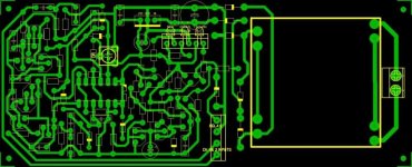
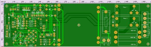
I'll be using two of these as they will go into monoblocks, however, the PCB caters for left and right channel monitoring in cases where I may use this board in a stereo amplifier.
I also set up the softstart circuit such that the main On/Off switch only switches on the small toriod (about 50mA) and the main power switching is via 10A relays.
At the RH end are terminal blocks for all mains connections... keep the mains wiring nice and tidy.
The 7VA toroid is 50mm x 50mm and the PCB is 50mm high by 170mm long.
I went double sided PCB so will send these out to be made.
Well, that was enjoyable.... 🙂
Well, the design and test part anyway..
The circuit has been breadboarded up, PIC code finished and all has been tested.... all works perfectly.
I'll be using two of these as they will go into monoblocks, however, the PCB caters for left and right channel monitoring in cases where I may use this board in a stereo amplifier.
I also set up the softstart circuit such that the main On/Off switch only switches on the small toriod (about 50mA) and the main power switching is via 10A relays.
At the RH end are terminal blocks for all mains connections... keep the mains wiring nice and tidy.
The 7VA toroid is 50mm x 50mm and the PCB is 50mm high by 170mm long.
I went double sided PCB so will send these out to be made.
Well, that was enjoyable.... 🙂
Attachments
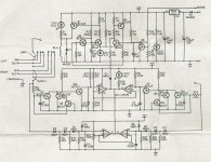
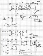
My Protector Schematics
Here is the circuit.
Sorry about handdrawn but I do not have a schematics package (never needed one todate).
Fairly simple circuit-wise.... all the smarts are in the PIC code.
Forgot to mark the transistors in the detection cct....they are all BC548 or 9s.
Best Regards
Here is the circuit.
Sorry about handdrawn but I do not have a schematics package (never needed one todate).
Fairly simple circuit-wise.... all the smarts are in the PIC code.
Forgot to mark the transistors in the detection cct....they are all BC548 or 9s.
Best Regards
Attachments
Looks neat too.
Be sure you will use nonpolar caps for dc. detect.
I buy recently 4 piece of UPC1237 (China) and only one work.
I make a new order for 4 piece and if will be the same I go to discrete transistors.
Be sure you will use nonpolar caps for dc. detect.
I buy recently 4 piece of UPC1237 (China) and only one work.
I make a new order for 4 piece and if will be the same I go to discrete transistors.
- Status
- Not open for further replies.
- Home
- Amplifiers
- Solid State
- Delay turn on circuit for amps