Simply putting component values into ltspice isnt the way to go.
You need to design a circuit taking into account wattages and SOA's and put those into ltspice.
You need to design a circuit taking into account wattages and SOA's and put those into ltspice.
Sometimes it does and sometimes it does not. If the problem is with the design itself and the models are accurate enough then the sim may break into oscillation. If you do not have a low enough value for time step then it may not be caught, the lower you go the longer the sim takes to run. I tend to sim with a maximum time step of 0.1uS if I'm wanting to be sure about things... Tony.
hi and thanks a lot for the very helpful advice. I wonder if there is a field of audio design where sim can give the most reliable results.
I am interested mainly to very simple circuits with very few bjts/fet and lately tubes as well.
For instance i have no clue and i would be extremely interested to know if there are models for tubes. That would be nice.
Last edited:
I like the simulator because I can try lots of 'what ifs' quickly. I will typically build a bench setup of the circuit and see how well measured results compare to those of the sim. The better the models reflect the real components, the better the sym correlates to what I see on the bench. I do analog type circuits, and have not tried to do anything in the digital realm at all. It's over my head.
Hi ! thanks again. I understand there are SW more refined available to designers. I wanted to post this question in the Lounge because i intended it as a poll ... to understand the popularity of this design tool. I understand many designers rely on them. Of course for using the tool rightly and be aware of its limitations competence is needed. I guess it depends also on the complexity of the circuit ... maybe the simpler ones are also easier to simulate?Sometimes it does and sometimes it does not. If the problem is with the design itself and the models are accurate enough then the sim may break into oscillation. If you do not have a low enough value for time step then it may not be caught, the lower you go the longer the sim takes to run. I tend to sim with a maximum time step of 0.1uS if I'm wanting to be sure about things. ... The sim is a great tool but at least with the ones available for free to us hobbyists they do have their limitations.
Tony.
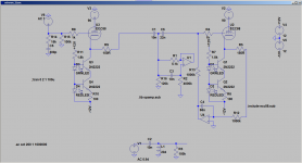
There are models for tubes.
See attached. I have not ever built a tube circuit, the attached is a sim of SY's Acheron circuit (a high pass filter using a gyrator), which I did when I was trying to understand how it worked.
Tony.
Great news as lately my interest in tube line stages is increased a lot
I had a look in the relevant section and i have seen thread on this topic.
As i said i am a beginner scared by the complexity of the task of using this SW.
I am still looking for a guide for using LTSpice very basic function.
I have no hopes to understand the theory ...
Simply putting component values into ltspice isnt the way to go.
You need to design a circuit taking into account wattages and SOA's and put those into ltspice.
You can also use (on OSX) ctrl+click to display the power and heat dissipation - not just voltage and current. Useful to help fill out wattage etc. Also there's nothing stopping you from adding test points and adding circuit components to detect & flag should specifications be breached. Just need a single line and a latch at the end - the circuits then set the latch high should they detect a problem. Then you see where the latch was set high on the graph.
Last edited:
Generally any circuit diagram is a simplified representation of reality - the same is to be expected from a simulation based on the circuit diagram and modelled components. It is on you to complete the modelling according to your needs. Simulation does not replace understanding of the circuitry, but maybe of great help in doing so.
Once I had a stability problem with a buck regulator due to poor pcb-layout. So I added a transformer to simulate magnetic coupling between output loop and input loop, fiddled with its values until the instability was simulated correctly. At this point I played with the sim and altered loop compensation until things became stable. Later on I changed the BOM of the circuit accordingly and this worked in mass production as well😉
Once I had a stability problem with a buck regulator due to poor pcb-layout. So I added a transformer to simulate magnetic coupling between output loop and input loop, fiddled with its values until the instability was simulated correctly. At this point I played with the sim and altered loop compensation until things became stable. Later on I changed the BOM of the circuit accordingly and this worked in mass production as well😉
Last edited:
Simulation tools are great, but no replacement for knowing circuit theory. If you don’t understand what you are simulating, than you will likely fall prey to the many ways a simulation can lie to you. Putting a schematic into a simulator like LTspice will give you the right answers if you set it up correctly and ask the right questions of it. Simulations have layers of underlying assumptions built into them that can be modified as needed to suite the problem being studied. Unless it’s a very simple cookbook circuit, I will simulate first before building.
Simulation tools are great, but no replacement for knowing circuit theory. If you don’t understand what you are simulating, than you will likely fall prey to the many ways a simulation can lie to you. Putting a schematic into a simulator like LTspice will give you the right answers if you set it up correctly and ask the right questions of it. Simulations have layers of underlying assumptions built into them that can be modified as needed to suite the problem being studied. Unless it’s a very simple cookbook circuit, I will simulate first before building.
Hi ! thanks a lot ... i see better now the problem. I don't know if a comparison with a flight simulator is valid. But in a simulator you still need to know the various tools and have at least a basic knowledge of the flight technique. Despite this, if I'm not mistaken, a driving simulator in general is an exceptional learning tool.
Again if I am not mistaken even the formula one drivers use it to get used to circuits they do not know before they even get on the racing car.
I don't understand how people don't get fascinated by them(i.e. sim sw).
For me they are exceptional tools. Of course you have to know how to use them. And they are not just a hammer that's clear.
Then there are probably design fields where the results are much more reliable than others.
But if the parts manufacturers supply the models it means that there are some crazy people who use them 🙄
Simulation tools are great, but no replacement for knowing circuit theory. If you don’t understand what you are simulating, than you will likely fall prey to the many ways a simulation can lie to you. Putting a schematic into a simulator like LTspice will give you the right answers if you set it up correctly and ask the right questions of it. Simulations have layers of underlying assumptions built into them that can be modified as needed to suite the problem being studied. Unless it’s a very simple cookbook circuit, I will simulate first before building.
This works both ways.
I have LTSpice not wanting to model TTL running at -132 (high) -137 (low) however when it calculates the reference trigger point it gets confused and sets the point to -269 not -134.5 (it fails to 1/2). This seems inbuilt and not part of the model.
Now should you try this - not really.. getting down to the that voltage with a coupling cap means your voltages lag as the rails drop quickly.. thus your 5V TTL is likely not to enjoy it's start up sequence (although in the order 500uS - the question then becomes will it work with ESD protection?).
There's also other things I see on many schematic such as not not ensuring the grid is clamped negative to the cathode on start up..
A better way of comparing the use of a driving simulator to an electronic simulator, to use a driving simulator you need to be a mechanical engineer to understand the applied load forces of the wheels, tyres, suspension and the stresses the engine and drivetrain has to endure whilst going around the race track to understand the data from the output of the simulator.Hi ! thanks a lot ... i see better now the problem. I don't know if a comparison with a flight simulator is valid. But in a simulator you still need to know the various tools and have at least a basic knowledge of the flight technique. Despite this, if I'm not mistaken, a driving simulator in general is an exceptional learning tool.
Again if I am not mistaken even the formula one drivers use it to get used to circuits they do not know before they even get on the racing car.
For example driving the simulator and the car drives off the track, is it because of driver error or mechanical failure. The engineer will be able to interpret the data to determine the temperature of the brakes was excessive causing brake failure but the driver could only say the car didn't stop, the same analogy applies to electronic simulations.
Without sufficient electronics knowledge how will you determine if the circuit you're simulating doesn't function correctly or provides erroneous data. All you will be able to say is the circuit doesn't work.
A simulator is not a magic tool to turn a non-functioning circuit into a fully operational circuit. Firstly an engineer will have to design a working circuit before its entered into the simulator. An engineer could derive various voltages and currents from a paper design manually using a calculator but a simulator can perform this function in a fraction of the time.
A better way of comparing the use of a driving simulator to an electronic simulator, to use a driving simulator you need to be a mechanical engineer to understand the applied load forces of the wheels, tyres, suspension and the stresses the engine and drivetrain has to endure whilst going around the race track to understand the data from the output of the simulator.... Without sufficient electronics knowledge how will you determine if the circuit you're simulating doesn't function correctly or provides erroneous data. All you will be able to say is the circuit doesn't work.
Hi i thought better and i think that the comparison is flawed. My bad.
I believe that theory must be known. It is the very basic knowledge how devices work .. the principles. So theory comes even earlier than simulation.
Thanks a lot,
to turn a non-functioning circuit into a fully operational circuit. Firstly an engineer will have to design a working circuit before its entered into the simulator.A simulator is not a magic tool
An engineer could derive various voltages and currents from a paper design manually using a calculator but a simulator can perform this function in a fraction of the time. [/QUOTE]
i understand better now. It is a tool for who knows what he/she is doing
Speaking of amps i am very concerned about stability. And what puzzles me most is the fact that a design stable at sim could be unstable in reality.
This is by far the sim weakest point. 🙁
A design that is not stable is not working at all.
. what puzzles me most is the fact that a design stable at sim could be unstable in reality.
This is by far the sim weakest point. 🙁
A design that is not stable is not working at all.
Circuit stability can be influenced by feedback compensation (control systems theory). A circuit maybe stable in the simulator but unstable in reality because of poor PCB layout design techniques.
A simulation is only as accurate as the data provided such as component modelling, an engineer will still need to build a prototype to verify circuit performance and functionality and will most likely make design and/or component changes as required. These are the types of problems that engineers will encounter.
Circuit stability can be influenced by feedback compensation (control systems theory). A circuit maybe stable in the simulator but unstable in reality because of poor PCB layout design techniques.
Thanks ! very interesting I wonder if all the circuits are sensible to lay-out or some more than others. For instance i am not interested in digital and circuits using smd parts. Let's take a classic Rotel integrated Will the lay-out have an impact on stability ? i changed the feedback resistor only and the amp became unstable. Maybe just a different bypassing cap had solved the issue ... i do not know. I have always to fight with too much gain.
Perfect ! this i have understood. Thanks again.A simulation is only as accurate as the data provided such as component modelling, an engineer will still need to build a prototype to verify circuit performance and functionality and will most likely make design and/or component changes as required. These are the types of problems that engineers will encounter
Do you mean you reduced gain by changing the feedback network? That sound more like a feedback compensation issue that should be simulatable without having to model the PCB traces.
When you simulate it with a transient run, you still either have to use a small minimum time step or be careful with what integration method you choose (see post #36). In either case you have to apply an excitation of some sort, like a small step.
When you simulate it with a transient run, you still either have to use a small minimum time step or be careful with what integration method you choose (see post #36). In either case you have to apply an excitation of some sort, like a small step.
It is a fact that reducing the gain by reducing the feedback resistor generally is a move towards instability. This is part of basic knowledge concerning negative feedback operation. A properly setup simulation would show this as well.
Hi ! yes ! i had an headphone amp with a decent sound. The idea was to use it to drive the power amp section of a Rotel ra930 ax little integratedDo you mean you reduced gain by changing the feedback network?
The preamp issue has always been my nightmare. Imho is easier to find a decent power amp than a decent line stage. I do not know why.
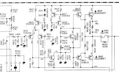
Anyway ... as the HP amp gain was like 10 times i thought to reduce the gain of the power amp by reducing the value of the FB resistor (R635 in the attached schematic)
I do not remember the value i used. (Maybe i should have increased R611 instead ?)
The amp was making some very low level sound and buzzing ... then the transformer started smoking I put a hand on the heatsink and i burnt my fingers 😱
that is very good indeed. It can save fingers 😀That sound more like a feedback compensation issue that should be simulatable without having to model the PCB traces.
When you simulate it with a transient run, you still either have to use a small minimum time step or be careful with what integration method you choose (see post #36). In either case you have to apply an excitation of some sort, like a small step
But now my approach would be completely different. Broadly speaking i see that power amp designs are in the end discrete power op-amp ?
Then the idea would be to start from a discrete op-amp of a decent preamp and use more powerful devices.
A close loop gain of 10 would be more than enough for me.
In this way i could use higher gain preamps, an approach that i much prefer ... to have more gain in the preamp.
This is what is done for instance in the First Watt design ? a low gain high current power amp that takes a signal already high in voltage and just pushes the speakers
I understand that what makes the sound is the Vgain stage ... then why even low power amp have so high gain ? weird
Maybe i am missing something
What is the rationale to have a very high open loop gain and then apply a lot of feedback to reduce it ? is it not better to start with a lower number of devices and lower open loop gain ? maybe it is a psrr issue ?
In the end i destroyed the amp. 🙁
Attachments
Last edited:
- Home
- Design & Build
- Software Tools
- About the use of simulation for circuit design.