National Instrument has made a "community edition" of LabVIEW 2020 available for free. You need to create an account (of course) and redo the license after a year; it's a fully functional "test and measurement" program development environment that works with GPIB, Serial and other USB connected hardware. Pretty good.
Regarding Audio test, there's not much you'll be able to do with it that hasnt been thought of and done already - considering the myriad of available audio test programs available in the last 20 years...
What you can do with it is create something specific to a particular need, that other general test system programmers wouldnt have possibly thought of -
Something like "When I clap my hands, give me a spectrum analysis of the sound I'm measuring in the moment just before the clap".
I'd be interested if anyone here installs and uses the LabVIEW "community edition" for audio test and measurement -
Thanks
What kind of ideas have you come up with in the audio that can be done with a layman like myself
Like all programming, it's tedious - even within the graphical program construction environment, where you "wire" "functions and structures" into a working program. You still have to think through every bit of the logic and functionality.
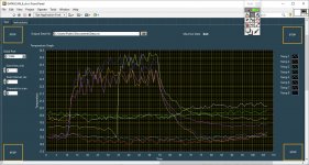
I've made simple things, like a speaker impedance sweep - using a remotely programmable function generator I couldnt afford to buy. Recently, I made an interface for a MSI Datascan 7221, a serial bus communication control 8 channel measurement device I picked up on ebay for $35. I can measure 8 J type TCs with it.
I did that mostly to see if I've completely lost it, or could still get some arbitrary piece of equipment functional from scratch. Fortunately, MSI still had enough docs on the device for me to figure out what to do communication and command wise. What I'll do with the completed GUI? Maybe measure temperatures in the garden raised beds next summer...
Attachments
Last edited:
So here's the beginning of an audio measurement application in LabVIEW. Whether a "lay" person could do this, well, I suppose that depends on how "lay" the person is. I'm supposedly with expertise in this and it's been with some determination that I've punched through to even this level.
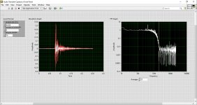
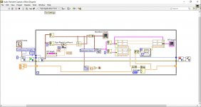
The attached pix show the UI panel and the "code", which is what's called the diagram part of the LabVIEW development environment. These two pieces are analogous to an analog instrument, with a panel containing knobs and switches, and the physical circuitry behind.
The time capture is a finger snap or clap from my laptop's mic, the FFT display is an averaged realtime response of a low pass filter provided by LabVIEW - also shown as the white trace in the time window. There's a s**t-ton of mathematical functions available to use, many of which are specifically for waveform processing.
LabVIEW provides a driver for sound card data acquisition. It says it can do stereo; at this point I've only used the laptop mic, which I assume is connected to provide mono in both channels. The architecture of the program consists of setting up the sound card parameters, starting the sound card, reading the data acquired repeatedly, then stopping the sound card and closing the connection to it.
The sound card read function provides two channels of sampled data, which consists of two "clusters" of 3 elements - a t0, a dt and an array of data samples - in an array. In my program, I break out each channel individually and run one through a low pass filter.
The lowpass frequency is controlled in a fancy way by sliding a cursor along the x-axis of the FFT display graph. As the program is running, you can slide the cursor and watch the effects of the filter. Ordinarily, the FFT would show both the input and filtered input on the same graph, but I took it a step further.
I did a ratio of each frequency band comprising the FFT, so that when output level = input level, the band amplitude is "1". This has the effect of showing what the filter does, regardless of input - which is hopefully some broadband signal. To further clarify the filters action, I arranged an averaging scheme - with a panel control for the # of averages.
The continuous data acquisition from the sound card is stopped when the input amplitude exceeds a threshold. Thus I can snap my fingers or clap to stop. I could put a "Stop" button on the panel more easily than stopping via signal analysis.
So let's say we can see what the filter is doing pretty clearly after the FFT ratio and averaging. Let's get rid of the filter and use a flat mic as the channel 2 source instead. Connect channel 1 to your speaker input (with appropriate padding), place the mic 1m in front of the speaker - and play some music. As the averaging settles, we should see the characteristic of the speaker - instead of the filter in my example.
Use a flat mic going into both channels. Place one, 1 m in front of a speaker, the other at your listening position. Play some music. As the averaging settles, we should see the "filter" characteristic of the room begin to show up. Averaging, of course, may not be the best way to suss out what this looks like, but because this is a full programming language, you can design any detector method you want. Like an averaging with fast attack and slow decay perhaps. Or different attack/decay times band by band as a function of frequency.
IMHO, LabVIEW should have done this free community version 20 years ago, as at this time all the other programing languages and their development environments have caught up and can do anything LabVIEW can do, with sufficient determination of the programmer - which you need anyway with LabVIEW. LabVIEW has its bugs and can present the typical computer "wrestling match" where you need to know the trick to get it to work. For example, I struggled getting the multi-mode FIR filter to work at all, before quitting that and going to the low-pass - which is just another FIR in a slightly different wrapper! WTF! You will encounter a lot of that, after all, it's a computer we're working with here and I know of no development environment where that isnt the case.
If anyone would like further clarification of how the diagram code works, feel free to reply. The low-pass FIR has 56 taps for example.
Attachments
Last edited:
Very impressive. However what can be done to make this useful? For me I would like to use this to capture the repose of a microphone to a spark discharge. I have most of the hardware but time for software. My plan is to capture the current waveform of the spark as a reference for the microphone.
Whenever I have looked at Labview it was pretty overwhelming. Even the download was huge.
Whenever I have looked at Labview it was pretty overwhelming. Even the download was huge.
National Instrument has made a "community edition" of LabVIEW 2020 available for free. You need to create an account (of course) and redo the license after a year; it's a fully functional "test and measurement" program development environment that works with GPIB, Serial and other USB connected hardware. Pretty good.
Whoa-- I missed this the first time around. Pretty decent way to get some ATE from your usb/gpib based equipment. Really cool.
Very impressive. However what can be done to make this useful? For me I would like to use this to capture the repose of a microphone to a spark discharge. I have most of the hardware but time for software. My plan is to capture the current waveform of the spark as a reference for the microphone.
Whenever I have looked at Labview it was pretty overwhelming. Even the download was huge.
Well, I had a fairly large reply all typed up and twitch-touched some key - all gone! It's after midnight; I'll try again tomorrow...
Very impressive. However what can be done to make this useful? For me I would like to use this to capture the repose of a microphone to a spark discharge. I have most of the hardware but time for software. My plan is to capture the current waveform of the spark as a reference for the microphone.
Whenever I have looked at Labview it was pretty overwhelming. Even the download was huge.
1. I assume that the spark current is transformable into acoustic output. Intuitively, it's a fast, short lived transient, which sounds like it would produce a flat frequency response - all frequencies at uniform level. Let's say you can fire this spark @ 10Hz and make repetitive captures of the current into a sound card. Take an averaged FFT of that (as the LabVIEW program I showed above does) and you get this nice, flaaaaat spectrum.
2. Then do the same thing on the microphone under test signal. Do the ratio of the spectrum band levels. As the LabVIEW program showed the canned, low pass filter response, it should show the "filter" between the spark current and the microphone signal - at least amplitude wise. Of course, I'm leaving out many details, such as how you level set the amplitudes of the two signals to get something meaningful in an absolute sense.
3. If you have the transform between spark current and acoustic output, say, from using a calibrated reference mic, that could be incorporated into the program. I did this one time to see microprocessor current from a voltage measurement, by 1st getting the impedance (mag/phase) of the power supply, looking into the uP socket. I even setup a "graphic eq" modifying the impedance data for tweaking - it was fun watching the square wave top tip to the left and right as I swung the phase of the fundamental to lead or lag. In real time of course!
Yes - it's a big download and a learning curve. I always liked programming in a similar way to drawing out a schematic diagram, versus writing a script in text. It can do a lot. The last thing I did professionally was a heat sink qualification system, with control loops on airflow and power dissipation. A few years ago, I tried analyzing stock market data, using LabVIEW to fetch a ticker's daily "Open, High, Low, Close" data from some Yahoo URL that's probably defunct now - it's just a time waveform to me. Mostly to prove you dont need hardware at all to do waveform analysis.
I figured out how to to all the averages, Bollinger bands, double bottoms and other crap that's supposed to help one predict the future from past behavior. Nonsense - the best you'll ever do from that stuff is 50/50 - before your broker and taxes takes their share.
Some web sites dont like you scraping their data, so they take it out of plain sight using some javascript or some such obfuscation. I thought I once saw a service that would convey any numerical information displayed in any way from any site, for automated analysis. So the net can be a data source for LabVIEW analytics; I was thinking of teaching LabVIEW that way (one time) to avoid all the specific test equipment setup hassle. The programming structure to get the data is conceptually the same either way - just substitute different functions in the same basic structure.
Last edited:
Whoa-- I missed this the first time around. Pretty decent way to get some ATE from your usb/gpib based equipment. Really cool.
Yes, it'll do serial communications and you can communicate with instruments having a network connection - among other things on the net. You can do vision stuff too with a camera - I was trying to read barcodes on trays moving along a conveyor at Amazon. The boss moved on, threw the copy of LabVIEW to these other guys (who reportedly never used it) and that was the end of that.
I once positioned a pingpong ball in a clear tube of flowing air between two pieces of arbitrarily placed tape markers using a camera. For fun, for the "bring your kid to work" day at Intel...
1. I assume that the spark current is transformable into acoustic output. Intuitively, it's a fast, short lived transient, which sounds like it would produce a flat frequency response - all frequencies at uniform level. Let's say you can fire this spark @ 10Hz and make repetitive captures of the current into a sound card. Take an averaged FFT of that (as the LabVIEW program I showed above does) and you get this nice, flaaaaat spectrum.
2. Then do the same thing on the microphone under test signal. Do the ratio of the spectrum band levels. As the LabVIEW program showed the canned, low pass filter response, it should show the "filter" between the spark current and the microphone signal - at least amplitude wise. Of course, I'm leaving out many details, such as how you level set the amplitudes of the two signals to get something meaningful in an absolute sense.
3. If you have the transform between spark current and acoustic output, say, from using a calibrated reference mic, that could be incorporated into the program. I did this one time to see microprocessor current from a voltage measurement, by 1st getting the impedance (mag/phase) of the power supply, looking into the uP socket. I even setup a "graphic eq" modifying the impedance data for tweaking - it was fun watching the square wave top tip to the left and right as I swung the phase of the fundamental to lead or lag. In real time of course!
There is a little info on the spark's acoustic waveform but not enough that I can predict it. I have calibrated microphones (to past 100 KHz) and my goal is to get frequency/phase response from the spark impulse. ECM and MEMs mikes are not suited to electrostatic calibration so acoustic is the only option. Few transducers get past 20-30 KHz without a lot of "anomalies". Low frequencies are generally not an issue so only the upper band. I can make a spark (at up to 60 Hz) in the middle of a ground plane which should be pretty clean. I'm using and older one of these: Universal Spark Generator, Daedalon(R) - Science First for the spark. I modified it with an external trigger so its more flexible.
I sat through an intro to Labview many years ago but it was just too much for too little at the time and the $4500 price was an issue. I'll download the new version and see how far I get. I have a lot of GPIB instruments to interface as well.
- Status
- This old topic is closed. If you want to reopen this topic, contact a moderator using the "Report Post" button.
- Home
- Design & Build
- Software Tools
- NI LabVIEW now FREE for personal, non-commercial use