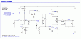
I have a few questions on how to use the LT Spice “LoopGain2.asc” model for open Loop gain analysis under these scenarios.
Output networks: I seem to remember reading that zobel networks and output inductors should be removed from the model? Is this correct? If they should be included, is it after Vi & Ii (net X)?
Bootstrapped VAS current source: Gain margin is different depending on whether the cap is connected before or after Vi & Ii. Which connection point is appropriate? I believe it is net Y in my example.
Transitional Miller Compensation (TMC): If the TMC resistor is connected after Vi & Ii, the AC plot looks odd. Should this be connected before Vi & Ii (net Y in my example)?
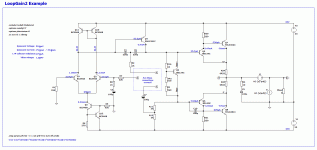
I attached an example from LT Spice XVII illustrating my questions. The example is based on Rod Elliot's P3a & P101. It is just an example for learning purposes. Not meant to be a working amplifier.
Thanks!
Attachments
I have a few questions on how to use the LT Spice “LoopGain2.asc” model...
...that zobel networks and output inductors should be removed from the model? Is this correct?
Hi Brian
No, not correct, you should keep the Zobel and output inductors.
Your placement of the probe is not quite correct either.
Redraw the circuit wired as it will be used, place the probe components as a "T" with labeled nodes and I will try to help.
Also, you could search my old posts with keyword "Tian", I have had discussions on this, especially with Damir (DadoD) and Paul (MCD99).
Best wishes
David
Last edited:
Revised file with Zobel Network added back. I think I see what you mean by the probe placement. I had it on the wrong side of my box indicating where the output networks would be.
I'll take a look at the other threads you mentioned over the weekend.
Thanks David.
I'll take a look at the other threads you mentioned over the weekend.
Thanks David.
Attachments
I'll take a look at the other threads you mentioned over the weekend.
Now I look back over them I see that it's pretty scattered.
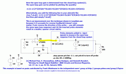
So here is a pic. of the usual placement.
Best wishes
David
...The placement of the probe is reversed from the instructions...
The probe measures a loop gain so it can be placed in different places around the loop and should still return the same results, but most people place it as shown because it looks more like it's in the feedback path.
I wrote the results "should" be the same but reality doesn't quite match theory, because there are second order effects that the Tian probe doesn't capture (need a more complicated, Middlebrook GFT probe for that).
Usually the difference is too small to matter but consistent placement will at least ensure any potential inaccuracy is consistent too.
I picked the example arbitrarily, then a close inspection showed there are a lot of potential feedback paths, not sure if this makes it a bad example because it's too complicated or a good one to show unexpected subtlety.
For instance, a bootstrapped current source is actually an example of positive feedback and may require some care if you have never considered it as such.
Best wishes
David
Last edited:
- Status
- This old topic is closed. If you want to reopen this topic, contact a moderator using the "Report Post" button.


