OK, I think I've made this work. Multiple Tian stability plots across the signal swing. Thanks to jcx and fas42 for assistance.
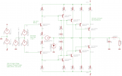
I have a 250W CFP output stage I'm working on. I wanted to break the CFP local loop to check GM & PM at several points on the output swing, from -80V to +80V. Here's what I did.
Nested .step sweeps:
.param dcin=0 prb=0
.ac dec 100 1 1e9
.step param prb list -1 1 ; Tian loopbreak probe V1 and I1; set prb=0 to turn off probe
.step param dcin list -78 -40 0 40 78 ; run Tian loopbreak at each of these voltages
One .func in the plot.defs file for each of the dcin values:
.func stb1() -1/(1-1/(2*(I(VI)@1*V(OUT)@2-V(OUT)@1*I(VI)@2)+V(OUT)@1+I(VI)@2))
.func stb2() -1/(1-1/(2*(I(VI)@3*V(OUT)@4-V(OUT)@3*I(VI)@4)+V(OUT)@3+I(VI)@4))
.func stb3() -1/(1-1/(2*(I(VI)@5*V(OUT)@6-V(OUT)@5*I(VI)@6)+V(OUT)@5+I(VI)@6))
.func stb4() -1/(1-1/(2*(I(VI)@7*V(OUT)@8-V(OUT)@7*I(VI)@8)+V(OUT)@7+I(VI)@8))
.func stb5() -1/(1-1/(2*(I(VI)@9*V(OUT)@10-V(OUT)@9*I(VI)@10)+V(OUT)@9+I(VI)@10))
I think I'll start a thread on this, so others can see it, cause it's useful.
Here's the schematic and plots for your viewing pleasure:
Attachments

Last edited:
Five years later, I got too busy with work to keep up my audio hobby. Meanwhile, my Mac, on which I did this work destroyed it's hard drive. This post is my only back-up of this work, so I'm sure glad I posted it here.
I replaced that Mac with a 6-core I7 running Windows 10. That allows me to use the full LTSpice. I was using Eagle for schematic capture before, but meanwhile I also bought a 1/2 price copy of Altium for schematics and board layout. I feel like I should open a consulting business doing board layouts for this investment.
Anyway, the simulation engine in Altium is pretty bad, from what I understand, and I can't get it to recognize PSPICE or SPICE3 models for transistors. I'll continue to netlist out to LTSpice.