I'm not sure, but I would set it at 20K and test some known value resistors. Maybe some other passive components once you've verified the resistors.
Umik and Omnimic are different hardware. Both are USB microphones, but Ombimic has different sensitivities for the two channels (managed by software) and uses a 3 terminal capsule for slightly better signal handling. And the measurement features of Omnimic software only work with its hardware.
A way to still have adjustability of an LPAD but without subjecting it to high amplifier power is to use a 6dB or so fixed resistor attenuator followed by an an adjustable lpad. Tweeters almost always have to be turned down more than 6dB, and with the fixed pad the lpad only sees 1/4 the power.

That makes sense - thanks for the suggestion. I will need about 12dB of attenuation.A way to still have adjustability of an LPAD but without subjecting it to high amplifier power is to use a 6dB or so fixed resistor attenuator followed by an an adjustable lpad. Tweeters almost always have to be turned down more than 6dB, and with the fixed pad the lpad only sees 1/4 the power.
The common low power L-Pads I have found to be crap. Very poor quality connections. The 100W versions seem to be better.
True. They get expensive though, and seem (to me at least) like un-necessary stuff as the power level to a tweeter driver itself is often on the order of milliwatts!
Hi Bwaslo,
When I used to use PCD, I would capture an FRD from the woofer, then tweeter, then combined. Then tweak the time delay on one of the drivers until the simulated combined matched the measured combined to perfectly - an acoustical interfergram method to get the acoustic centers offset precisely. Once this was done, one knows with certainty that the simulator will predict the XO response accurately.
Now, recently when I use Xsim, I seem to get pretty good results without ever bothering to do the acoustic center offset adjustment with the combined drivers. Is that still needed, or was I just getting lucky? I think it is because the mic measurements are not referenced to an absolute time delay.
Right, if the mic measurements already include the relative delay between the drivers (or absolute delay) then the simple alignment step isn't needed, you can go right to crossover simulation. Same if the drivers are already physically delay aligned (pretty much means a waveguide arrangement, with a few exceptions).
The way most people do it (with non-looped-back type measurements) is to take three full spectrum measurements, Driver A, Driver B, and Drivers A and B playing together. Then simulate Driver A and Driver B together in Xsim (just the two drivers connected to the power amp) and adjust the delay of the lower frequency driver until the simulation matches the 'playing together' measurement, which gives you the actual relative delay to design with.
The way most people do it (with non-looped-back type measurements) is to take three full spectrum measurements, Driver A, Driver B, and Drivers A and B playing together. Then simulate Driver A and Driver B together in Xsim (just the two drivers connected to the power amp) and adjust the delay of the lower frequency driver until the simulation matches the 'playing together' measurement, which gives you the actual relative delay to design with.
I was able to get my test box working well and produced the phase plots for my drivers in the enclosure. Now I get to plug the zma data in and try again at a x-over design. Is it true that the 41Hz low between the spikes on the woofer indicates the tuning of the ported enclosure? If so, I missed 55Hz by a fair amount and 41Hz does not look good in WinISD. I bet someone is about to tell me I need to get the box tuning fixed first and pull new phase plots before moving to the x-over? 🙁.
Attachments
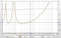

I was able to get my test box working well and produced the phase plots for my drivers in the enclosure. Now I get to plug the zma data in and try again at a x-over design. Is it true that the 41Hz low between the spikes on the woofer indicates the tuning of the ported enclosure? If so, I missed 55Hz by a fair amount and 41Hz does not look good in WinISD. I bet someone is about to tell me I need to get the box tuning fixed first and pull new phase plots before moving to the x-over? 🙁.
yeah, that's the box tuning frequency. Ideally you'd fix that before doing the crossover, but realistically not many crossovers are doing anything down around 55Hz or lower (would take huge low-resistance inductors or capacitors). So you can go ahead with the crossover design, but do retune the box (make the ports shorter or wider) before you do much listening.
Thanks, Bill. The two tuning ports are just the thickness of the 1.25" front baffle, so I knew getting the diameter exactly right was going to be tricky. The good news is that I can simply use a trim router and add a small radius to the openings, re-test, and then keep taking a little more until the tuning is right. Even better news is that I now know how to test to validate that I have a box tuned precisely where I want it! It's always seemed a bit of a guess to calculate how much interior volume is taken by the drivers, x-overs, bracing, etc. I have several other homemade speakers I plan to go back and test now that I know how.
Thank you very much for the awesome software and even more for the awesome personal support and help that you provide. I'm really grateful.
Tom

Thank you very much for the awesome software and even more for the awesome personal support and help that you provide. I'm really grateful.
Tom

Hmmmm. I thought that the bass reflex tuning point was shown as the low point between the two impedance peaks. Putting yours right about 41Hz.
Am I wrong?
Am I wrong?
I was able to get my test box working well and produced the phase plots for my drivers in the enclosure.... Is it true that the 41Hz low between the spikes on the woofer indicates the tuning of the ported enclosure? If so, I missed 55Hz by a fair amount.....
Hi Pano. I'm not sure I understand your question. I was commenting that it seems to be tuned to 41Hz when I was shooting for 55Hz.Hmmmm. I thought that the bass reflex tuning point was shown as the low point between the two impedance peaks. Putting yours right about 41Hz.
Am I wrong?
I'd like to post this crossover for comments. I added some padding to the woofer to bring down the huge 30Ω spike @ 80Hz. I don't know if that is considered bad practice, or not, and would appreciate any scrutiny. The HF horn FR is not very smooth and it took a couple of notch filters to tame it. Finally, the pad on the HF is not the exact values needed, but will be adjusted to maintain impedance.
My concerns:
- Will padding the woofer as I have done to even out the impedance spike harm dynamics? I realize it will reduce efficiency.
- Excluding cost, at what point does adding complexity to the x-over do more harm than good? I know that a 3dB spike/dip will be audible, but so will phase changes that the solution introduces.
- I know nothing about time/phase alignment and not sure what needs to be done to improve this loudspeaker performance.
- I see references to impulse response. Is that something I need to learn about and incorporate into a successful design?
Thanks for your comments and input.
Tom
Tom,
Post up your XSim .dxo project file and you may get some very specific help.
Overall I think your result here looks great.
Also I'd like to suggest you take a look at Wayne Parham's Crossover Electronics 101 and the other documents linked here:
Pi Speakers - unmatched quality and state-of-the-art performance
Last edited:
No bad, but that impedance dip around 10kHz seems kind of brutal. I'd rework the tweeter section, maybe put the notches across the driver itself rather than suck current from so close to the power amp. But like Mazza said, just attach your .dxo file and then everyone can easily run it and play with it.
No bad, but that impedance dip around 10kHz seems kind of brutal. I'd rework the tweeter section, maybe put the notches across the driver itself rather than suck current from so close to the power amp. But like Mazza said, just attach your .dxo file and then everyone can easily run it and play with it.
Yes, I tried as much as I could to bring that up and couldn't figure out how to do it without other bad results. I appreciate the help!
Wasn't sure if this is how most people do it, but it wouldn't allow me to attach the .dxo file saying it was too large, so I zipped it.
View attachment eWave-Mod2.zip
- Home
- Design & Build
- Software Tools
- XSim free crossover designer