And now for something completely different … referring to the 2015 … 2021 thread “Improve a Rotel amp THD by 20dB! “ and also referring to Monthy Python, of course.
Yamaha AX590 / AX592 / AX870 and AX890’s are not so bad amplifiers, but come along with some quite hefty flaws and quirks. E.g. there is no input pair’s degeneration. And amongst other, at first sight obscure twists, Yamaha has completely messed up the thermal design in all of these series with their’s smallish internal heatsinks and lowish idling current. Funny also to see how much space was internally wasted inside the bigger housings of the AX870/AX890: The “higher” model’s boxes are big not to contain better/more technical functionality, but only for prestige’s sake. Even the slightly bigger headsinks of the AX870/AX890 would neatly fit into the case of an AX590/592. The buyer just got a prime portion of a lot of air for her/his spent extra cash.
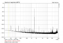
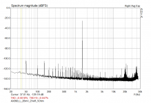
Just for interest, I gave the AX890 a slight twist on the Vbias trimmer, increasing the idle current of the power transistors to a theoretically more correct value. The Re’s are 0.22Ohm, and I increased Vre from much too low “Yamaha-standard” 5mV … 6mV to some theoretical correct value of approx. 26mV. This measure alone has a very decent effect on thd. So this might be a simple, effictient mod:
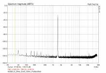
Measurements were taken with a sinewave signal of 1.5kHz, at 2Vrms out along with an 5Ohm output resistor. THD is 0.0074% at 6mV and 0.0018% at 26mV. The 3rd harmonic in both graphs seems to be a consequence of the non-degenerated input pair. At 6mV, there is a prominent spike of 2nd harmonic distortion, and also a smaller spike of 4th harmonic distortion. All other spikes above 1k5 are measuring artefacts.
Beware: This is a “hot mod”, as at +-60V and 2*120mA each heatsink has to deal with approx 25W … 30W while idling. So with it’s 2 channels, this glutton now draws hefty 60W while idling. I think that the addition of a big, slow rotating, silent ventilator like the one’s found in multimedia PC’s would be necessary to keep things cool enough inside a “productive” amplifier.
In listening tests the “hot” version appeared a wee bit more immersive than the “cool” version. But it is only, while notable, a slight difference. And also autosuggestions plays it’s role, as the test was not blinded.
After having blamed Yamaha in the intro: You may see it this way - Yamaha seems wisely to have chosen 5mV as a compromise value. To avoid the whole system from getting too hot. In this aim, some “poor” 25mA idling current for each output transistor pair might be a “sweet spot”. Because, on the other side, further reducing the idling current gives rise to a whole series of higher order (n=4 ...) harmonic distortions. So maybe, looking differently at it, Yamaha after all made a wise choice, at least an ecologically sane one. One of D.Self’s design is the “Trimodal Amplifier”, a switching Class A or B design, in which he jokingly suggests a switch labelling “Winter” and “Summer”. Winter for class A, Summer for Class B. The same might go for this kind of Vbe tweaking.
Yamaha AX590 / AX592 / AX870 and AX890’s are not so bad amplifiers, but come along with some quite hefty flaws and quirks. E.g. there is no input pair’s degeneration. And amongst other, at first sight obscure twists, Yamaha has completely messed up the thermal design in all of these series with their’s smallish internal heatsinks and lowish idling current. Funny also to see how much space was internally wasted inside the bigger housings of the AX870/AX890: The “higher” model’s boxes are big not to contain better/more technical functionality, but only for prestige’s sake. Even the slightly bigger headsinks of the AX870/AX890 would neatly fit into the case of an AX590/592. The buyer just got a prime portion of a lot of air for her/his spent extra cash.
Just for interest, I gave the AX890 a slight twist on the Vbias trimmer, increasing the idle current of the power transistors to a theoretically more correct value. The Re’s are 0.22Ohm, and I increased Vre from much too low “Yamaha-standard” 5mV … 6mV to some theoretical correct value of approx. 26mV. This measure alone has a very decent effect on thd. So this might be a simple, effictient mod:
Measurements were taken with a sinewave signal of 1.5kHz, at 2Vrms out along with an 5Ohm output resistor. THD is 0.0074% at 6mV and 0.0018% at 26mV. The 3rd harmonic in both graphs seems to be a consequence of the non-degenerated input pair. At 6mV, there is a prominent spike of 2nd harmonic distortion, and also a smaller spike of 4th harmonic distortion. All other spikes above 1k5 are measuring artefacts.
Beware: This is a “hot mod”, as at +-60V and 2*120mA each heatsink has to deal with approx 25W … 30W while idling. So with it’s 2 channels, this glutton now draws hefty 60W while idling. I think that the addition of a big, slow rotating, silent ventilator like the one’s found in multimedia PC’s would be necessary to keep things cool enough inside a “productive” amplifier.
In listening tests the “hot” version appeared a wee bit more immersive than the “cool” version. But it is only, while notable, a slight difference. And also autosuggestions plays it’s role, as the test was not blinded.
After having blamed Yamaha in the intro: You may see it this way - Yamaha seems wisely to have chosen 5mV as a compromise value. To avoid the whole system from getting too hot. In this aim, some “poor” 25mA idling current for each output transistor pair might be a “sweet spot”. Because, on the other side, further reducing the idling current gives rise to a whole series of higher order (n=4 ...) harmonic distortions. So maybe, looking differently at it, Yamaha after all made a wise choice, at least an ecologically sane one. One of D.Self’s design is the “Trimodal Amplifier”, a switching Class A or B design, in which he jokingly suggests a switch labelling “Winter” and “Summer”. Winter for class A, Summer for Class B. The same might go for this kind of Vbe tweaking.
Attachments
... Funny also to see how much space was internally wasted inside the bigger housings of the AX870/AX890: The “higher” model’s boxes are big not to contain better/more technical functionality, but only for prestige’s sake. Even the slightly bigger heatsinks of the AX870/AX890 would neatly fit into the case of an AX590/592. The buyer just got a prime portion of a lot of air for her/his spent extra cash. ...
Meanwhile I found out how to make the best of all this space - Fill it with something useful.
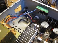
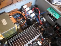
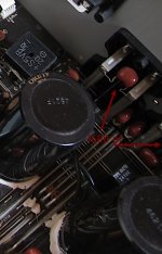
As the heatsinks got too hot at the increased (corrected !) bias setting of 26mV, and as I do not need some 200W of output, and since I found the hum behavior of the AX 890 not really brillant ... I performed some more tweaking. This time slightly more engaged than twisting two trimmers.
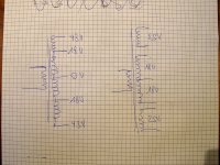
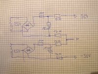
The original transformer has two (common) null taps, two approx. 18V-0V-18V AC taps and two approx 43V-0V43V AC taps. Partially dismantling the transformer, it is easily possible to retain the 18V-0V-18V taps and to disconnect two 25V windings originally soldered to the 18V taps in order to total 43V. The transformed transformer now has three galvanically isolated outputs. One 18V-0V-18V output and two 25V outputs.
These two 25V AC transformer outputs were each connetcted to two individual rectifier bridges and two capacitor reservoirs of 12mF from another dismantled AX870. The resulting +/-36V outputs of the PreRectifier were fitted with 0.11ohm resistors, and the common ground was also formed by the midpoint of two 0.11 ohm resistors. This way, the heavyiest currrent load from the primary rectifying process would be localized between these very first capacitors on the PreRectifier. And no more on the main amplifier board.
The 36V-0-V-36V DC outputs of the PreRectifier now do supply the regular and former 43V-0V-43V AC inputs on the main board. As in terms of a minimal invasive modification no changes were performed on the main board itself, this DC input supply passes once again a rectifier bridge (e.g. the originally fitted), feeding then into the regular onboard reservoir capacitors.
The result is manyfold quite nice, and in terms of hum even quite impressive: there is a very pleasing improvement of hum rejection by -20dB. I would not have expected so much. Secondly, because of the lowered supply voltage (from originally some 60V now to 36V), the temperature of the heatsinks now has become reasonable with no other modification needed. What was intended.
Attachments

https://www.bequiet.com/de/casefans/3706
Das ist sehr leise, besonders wenn es nicht max.
Legen Sie auf dünne / weiche Gummipuffer, direkt auf / zwischen die Kühler.
Dann kann man den Ruhestrom schön einstellen.
Das ist sehr leise, besonders wenn es nicht max.
Legen Sie auf dünne / weiche Gummipuffer, direkt auf / zwischen die Kühler.
Dann kann man den Ruhestrom schön einstellen.
That was an oversight, could you please send me a copy, hadn't saved the texts....
"Just for interest, I gave the AX890 a slight twist on the Vbias trimmer, increasing the idle current of the power transistors to a theoretically more correct value. The Re’s are 0.22Ohm, and I increased Vre from much too low “Yamaha-standard” 5mV … 6mV to some theoretical correct value of approx. 26mV. This measure alone has a very decent effect on thd. So this might be a simple, effictient mod:"
Hi, could you please put pictures for the measuring points...? Thanks
Hi, could you please put pictures for the measuring points...? Thanks
https://www.bequiet.com/de/casefans/3706
This is very quiet, especially when it is not max.
Put on thin / soft rubber pads, directly on / between the radiators.
Then you can adjust the quiescent current nicely.
This is very quiet, especially when it is not max.
Put on thin / soft rubber pads, directly on / between the radiators.
Then you can adjust the quiescent current nicely.
Output Cs, reduced to 1600 pf.
Speaker cable, soldered directly there.
Coupling Cs, bypass with 2x 4.7 MKP each.
PSU electrolytic capacitors bypass 4.7 µf MKP each, gladly replaced by 22,000 µf
PSU electrolytic capacitors (driver) 1,500µf plus 4.7 µf MKP, plus 0.01 µf
negative feedback Cs 4.7 µf + 0.01 µf bypass
Speaker cable, soldered directly there.
Coupling Cs, bypass with 2x 4.7 MKP each.
PSU electrolytic capacitors bypass 4.7 µf MKP each, gladly replaced by 22,000 µf
PSU electrolytic capacitors (driver) 1,500µf plus 4.7 µf MKP, plus 0.01 µf
negative feedback Cs 4.7 µf + 0.01 µf bypass
Attachments
Sorry, no. No pictures. You instead may download the service manual of the AX870, because 1. there is no downloadable service manual for the AX890 around, and 2. the AX870 and AX890 are similarly built."Just for interest, I gave the AX890 a slight twist on the Vbias trimmer, increasing the idle current of the power transistors to a theoretically more correct value. The Re’s are 0.22Ohm, and I increased Vre from much too low “Yamaha-standard” 5mV … 6mV to some theoretical correct value of approx. 26mV. This measure alone has a very decent effect on thd. So this might be a simple, effictient mod:"
Hi, could you please put pictures for the measuring points...? Thanks
Thank you.Sorry, no. No pictures. You instead may download the service manual of the AX870, because 1. there is no downloadable service manual for the AX890 around, and 2. the AX870 and AX890 are similarly built.
But also many thanks for the tip, I had completely forgotten (Vbias trimmer), in this case, a missing listening pleasure came into the amplifier.
")
What do you think of my other small modifications?
Especially also the Cs in the output.
This specific C-mod certainly was and still is a full success! Let me explain my reasoning for this statement: Audio DIY primarly is for personal fun and for satisfaction. And you certainly had a lot of fun, first while thinking about possible modding options, and then you also had fun while modding your Amp the way you did. And you certainly enjoy now satisfaction having a personally modded amp now. Furthermore, this makes your music sound better than before after this mod. That's why I think it's a success. You have fun and satisfaction DIY-ing your gear, and this is it. Enjoy!... What do you think of my other small modifications?
Especially also the Cs in the output. ...
- Home
- Amplifiers
- Solid State
- Improve a Yamaha amp THD by 12 dB!