I have a Heathkit IP-32 regulated bench supply, which I’m planning on converting to a 3 wire cord. First question: Are there any potential problems with that? I might add the usual Bryston/ESP ground isolation (parallel resistor, cap and diodes). This (ridiculously thorough) video touches on 2 wire vs. 3 wire, and he decides against 3 wire without giving detailed reasoning: Tools For The Bench- High Voltage Power Supply Repair! - YouTube
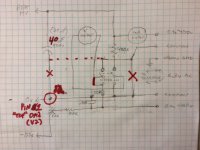
2nd Question: I found a couple of differences between this build and the schematics I’ve found online. My hand-drawn partial schematic attempts to show this. The B+ and C- commons are not tied together at the output, instead the C- common is connected to pin #1 of the upper 0a2 tube (the pin on the rectifier side of the pin 1-5 connection inside the 0a2). Also there’s a jumper on the meter switch between one side of the meter and the 150k resistor to C-. What could be the purpose of that? On my diagram the changes are marked in red. Ignore the red circle. The change from 40uF from 20uF on the output is based on what I had on hand when I rebuilt this thing 5 years ago. It was purchased from an estate and appeared original at the time, I replaced all caps, the selenium diode, and one out-of-spec resistor. I’ve used it to power some preamp and driver circuits (B+ only), and to match power tubes for DC bias (using both B+ and C-), and haven’t noticed any problems.
Original schem. here: HEATHKIT IP-32 POWER SUPPLY SCH Service Manual download, schematics, eeprom, repair info for electronics experts
Attachments
Generally you would earth the chassis to the ground wire on the power cord, then at the output you'd have the B+ common, B- positive, and an earth banana jack all next to each other so you can configure things as you'd like.
The output common connecting to pin 1 of the 0A2 is because the negative power supply has a pair of 0A2 regulators in series to make a -300V regulated rail. This -300V rail appears to be necessary to provide adquate adjustment range for the HV section.
The output common connecting to pin 1 of the 0A2 is because the negative power supply has a pair of 0A2 regulators in series to make a -300V regulated rail. This -300V rail appears to be necessary to provide adquate adjustment range for the HV section.
Ground the negative of the supply to the chassis along with earth ground on your power cord. Call it a day.
I'm leaning towards that plan, and then opening the fridge

Generally you would earth the chassis to the ground wire on the power cord, then at the output you'd have the B+ common, B- positive, and an earth banana jack all next to each other so you can configure things as you'd like.
The output common connecting to pin 1 of the 0A2 is because the negative power supply has a pair of 0A2 regulators in series to make a -300V regulated rail. This -300V rail appears to be necessary to provide adquate adjustment range for the HV section.
Yes, there are separate output posts for the 2 commons (which are tied together either directly in the schematic, or through the 0a2 in this example) and a chassis ground post, which has a jumper to connect to the B+ common (recommended in the manual also.)
Yes, the -300v serves as both the reference for the B+ voltage regulator and also the raw voltage for the adjustable C- output.
All thinks considered, i would advice against grounding the negative of the high voltage output, for the simple reason you wont be able to put two identical units in series anymore.
Safety grounding the chassis is a must, these are rather old cheap transformers, and i wouldn't trust my life on those.
Safety grounding the chassis is a must, these are rather old cheap transformers, and i wouldn't trust my life on those.
All thinks considered, i would advice against grounding the negative of the high voltage output, for the simple reason you wont be able to put two identical units in series anymore.
Safety grounding the chassis is a must, these are rather old cheap transformers, and i wouldn't trust my life on those.
Funny you should mention the transformers. One of mine did short out before. Luckily I was able to buy a second parts unit at a hamfest.
All thinks considered, i would advice against grounding the negative of the high voltage output, for the simple reason you wont be able to put two identical units in series anymore.
Safety grounding the chassis is a must, these are rather old cheap transformers, and i wouldn't trust my life on those.
*Looks over at Eico 1030 with original ungrounded zip-cord*
All thinks considered, i would advice against grounding the negative of the high voltage output, for the simple reason you wont be able to put two identical units in series anymore.
Safety grounding the chassis is a must, these are rather old cheap transformers, and i wouldn't trust my life on those.
Safety grounding has been completed. The circuit common to chassis ground connection remains the jumper on the front panel.
- Status
- This old topic is closed. If you want to reopen this topic, contact a moderator using the "Report Post" button.
- Home
- Amplifiers
- Tubes / Valves
- Heathkit IP-32 regulated supply