Hello Everyone
I have been a lurker for a good while on this site, but this will be my first post. I have looking for a DIY audio project and not quite found anything that will fit my needs/desires but that also meets my minimal skills, particularly when it comes to woodworking. I have been doing a lot of reading and think I have come up with an interesting concept that I can execute but have got to the point where I have some questions that I am hoping the community might be able to help with before I plow into making a bunch of simple mistakes.
Quick bit of background, I have been keen to find a good single driver speaker solution based on a fairly efficient driver. I recently built a pair of Bottlehead's Monamour mono-block SET amps based on the 2A3 tube which are great but max out at about 6-7 watts depending on tube choice.
Of all the designs I looked at on here (and there is a ton of great information which makes for lots of fun reading) the one I was drawn to most was the BIB. With the BIB calculator provided I was quickly able to get a handle on the math and start exploring drivers and cabinet sizes that might work for me. The challenge I found was the distinct lack of WAF. I do have my own space for my speakers, but still when you get into larger drivers the BIB box does become very imposing.
I started exploring alternate box shapes that could make the BIB a bit more "interesting" while not adding too much complexity to the build. I went through a bunch of iterations of trying the fold the line in different ways but nothing really worked and just added unnecessary complexity.
Finally I settled on the idea of creating a BIB Pipe. Basically I would try to find a good match for a piece of commercially available PVC pipe and build a cone to place in the center of the pipe. With the cone expanding downwards into the pipe, I simulate a folded cone where instead of just folding around a single axis like the standard BIB, the cone folds in all directions and the line returns back up expanding at the same rate as the cone gets smaller again.
Whilst this initially may sound incredibly complex, the math is no different in my mind to the standard BIB when you have a shape of a defined line length, a defined terminus area, that is increasing in cross-sectional area linearly along it's length.
As far as construction I am planning to do most of the complex design on a computer and 3D print the more challenging components. I should perhaps also admit that I have never done any 3D printing, but again there is a ton of information in the online communities so I am sure I can get over that hurdle.
There are however some challenges. I have tried to tackle a few of them but I am at the point where I could really use some input from the community on some of these things which are more basic in terms of which principles are strict and which have some flexibility to be manipulated.
1) How precise does the line length need to be?
Based on my testing of a few different drivers, the best fit for my needs came out be the FE168EZ. Per the BIB calculator I need to shoot for a line length of 132.01". The question is how accurate does that need to be. While the base concept is quite simple there are a few elements which may influence the final line length which I may not be able to fully account for. How far out can I be in terms of line length tolerance without impact the overall output?
2) How linear does the cross sectional area expansion need to be?
There is one design element in particular, the speaker driver box which will connect the driver on the outside of the main pipe to the cone on the inside which "consumes" cross sectional area from the main pipe cavity. I have attempted to account for this by increasing the ID of the main pipe at this point, but chose to only pick a few points and make an approximation of the cross sectional area at these points. I don't expect the effect to be a significant compression of the pipe, but the expansion may be less linear in this area. Do I need to go back and really focus on ensuring the expansion is as linear as possible or is a bit of variation OK?
3) The big concern. The design call for the driver to be mounted in a box with the back of the box pinched down to match the width of the cone at the Zdriver distance. In the BIB itself the driver is fully sitting in the line, whereas in my concept the driver is sitting fully in the box which is connected to the line. My intention was to stuff the box and hope that the restriction would not cause issues either in the driver itself or the coupling between the driver and the line. The other issue I can't determine is, assuming the first point is not an issue, should I include the distance from the back of the driver to the center of the cone in my line length calcs, or do I simply treat the point where the driver box and the cone intersect as the Zdriver point and treat the whole box separately from the line. My concern is that if I take that approach, the effective output of the driver enclosed in a stuffed box may have a different effective Fr leading to a different line length requirement. But this is where my knowledge falls apart and I am frankly grasping at straws and flailing with my lack of understanding.
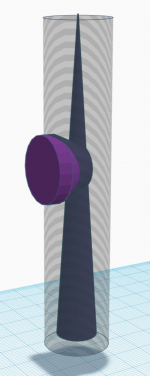
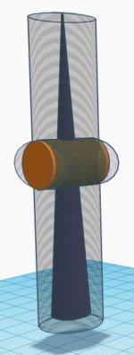
I really think if a couple of these fundamentals can be solved this could turn into a really good design. I have started doing some of the CAD work and have attached a couple of pictures of my initial designs. For context the commercial pipe will be SCH40 10" PVC and the whole finished speaker will be about 70 inches tall.
Alternatively I could be in way over my head and you all might be able to save me a bunch of wasted time and effort trying to build something which is doomed for failure from the outset.
Apologies for the incredibly long first post and thanks in advance for any and all feedback.
Phil
I have been a lurker for a good while on this site, but this will be my first post. I have looking for a DIY audio project and not quite found anything that will fit my needs/desires but that also meets my minimal skills, particularly when it comes to woodworking. I have been doing a lot of reading and think I have come up with an interesting concept that I can execute but have got to the point where I have some questions that I am hoping the community might be able to help with before I plow into making a bunch of simple mistakes.
Quick bit of background, I have been keen to find a good single driver speaker solution based on a fairly efficient driver. I recently built a pair of Bottlehead's Monamour mono-block SET amps based on the 2A3 tube which are great but max out at about 6-7 watts depending on tube choice.
Of all the designs I looked at on here (and there is a ton of great information which makes for lots of fun reading) the one I was drawn to most was the BIB. With the BIB calculator provided I was quickly able to get a handle on the math and start exploring drivers and cabinet sizes that might work for me. The challenge I found was the distinct lack of WAF. I do have my own space for my speakers, but still when you get into larger drivers the BIB box does become very imposing.
I started exploring alternate box shapes that could make the BIB a bit more "interesting" while not adding too much complexity to the build. I went through a bunch of iterations of trying the fold the line in different ways but nothing really worked and just added unnecessary complexity.
Finally I settled on the idea of creating a BIB Pipe. Basically I would try to find a good match for a piece of commercially available PVC pipe and build a cone to place in the center of the pipe. With the cone expanding downwards into the pipe, I simulate a folded cone where instead of just folding around a single axis like the standard BIB, the cone folds in all directions and the line returns back up expanding at the same rate as the cone gets smaller again.
Whilst this initially may sound incredibly complex, the math is no different in my mind to the standard BIB when you have a shape of a defined line length, a defined terminus area, that is increasing in cross-sectional area linearly along it's length.
As far as construction I am planning to do most of the complex design on a computer and 3D print the more challenging components. I should perhaps also admit that I have never done any 3D printing, but again there is a ton of information in the online communities so I am sure I can get over that hurdle.
There are however some challenges. I have tried to tackle a few of them but I am at the point where I could really use some input from the community on some of these things which are more basic in terms of which principles are strict and which have some flexibility to be manipulated.
1) How precise does the line length need to be?
Based on my testing of a few different drivers, the best fit for my needs came out be the FE168EZ. Per the BIB calculator I need to shoot for a line length of 132.01". The question is how accurate does that need to be. While the base concept is quite simple there are a few elements which may influence the final line length which I may not be able to fully account for. How far out can I be in terms of line length tolerance without impact the overall output?
2) How linear does the cross sectional area expansion need to be?
There is one design element in particular, the speaker driver box which will connect the driver on the outside of the main pipe to the cone on the inside which "consumes" cross sectional area from the main pipe cavity. I have attempted to account for this by increasing the ID of the main pipe at this point, but chose to only pick a few points and make an approximation of the cross sectional area at these points. I don't expect the effect to be a significant compression of the pipe, but the expansion may be less linear in this area. Do I need to go back and really focus on ensuring the expansion is as linear as possible or is a bit of variation OK?
3) The big concern. The design call for the driver to be mounted in a box with the back of the box pinched down to match the width of the cone at the Zdriver distance. In the BIB itself the driver is fully sitting in the line, whereas in my concept the driver is sitting fully in the box which is connected to the line. My intention was to stuff the box and hope that the restriction would not cause issues either in the driver itself or the coupling between the driver and the line. The other issue I can't determine is, assuming the first point is not an issue, should I include the distance from the back of the driver to the center of the cone in my line length calcs, or do I simply treat the point where the driver box and the cone intersect as the Zdriver point and treat the whole box separately from the line. My concern is that if I take that approach, the effective output of the driver enclosed in a stuffed box may have a different effective Fr leading to a different line length requirement. But this is where my knowledge falls apart and I am frankly grasping at straws and flailing with my lack of understanding.
I really think if a couple of these fundamentals can be solved this could turn into a really good design. I have started doing some of the CAD work and have attached a couple of pictures of my initial designs. For context the commercial pipe will be SCH40 10" PVC and the whole finished speaker will be about 70 inches tall.
Alternatively I could be in way over my head and you all might be able to save me a bunch of wasted time and effort trying to build something which is doomed for failure from the outset.
Apologies for the incredibly long first post and thanks in advance for any and all feedback.
Phil
Attachments

It is not entiely clear from your description & pictures what this box will look like but a couple points:
The length in a BIB is not overly critical.
Like the Metronome a cone leads to a quadratic expansion. In practice the difference between the quadratic taper and a linear taper is not large enuff to worry about.
The stub you have added to mount the driver, should be as short as possible, the backside should be flush with the interior of the pipe, and should be substantially larger diameter than the driver to avoid early reflections.
dave
Yeah, not sure I follow, though WRT horn tapers; right, the BIB has parallel walls on one side, flat board taper on the other = parabolic, but the Metronome's is a flat board taper on both sides = conical [linear taper?].
As you note, not a significant taper response difference unless extremely long, but technically correct for documentation.")
GM
As you note, not a significant taper response difference unless extremely long, but technically correct for documentation.
GM
Thanks everyone for the responses.
Let me start by reiterating I have no background in speaker design theory and almost no technical understanding other than throw together a few different design elements to try and make something "cool".
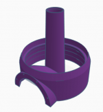
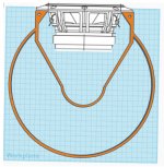
Having said that, I have attached a very rough sketch of what I conceived to be the overall concept in my head. Proportionally the end result will be much taller and narrower than shown but I wanted to just rough it to show the concept. The FE168e∑ design yielded an OD of the outer pipe at 10.75" with a total speaker height of about 70".
The link to the Metronome page was actually very helpful. If you look at the "Conehead" pic what I am attempting to do is take the top part of the cone (above the blue line) and fold it back into the lower section. In my head this was very similar to the BIB which essentially takes a Voigt pipe shape and folds it in the middle to condense the overall dimensions (I know its technically definitely not that, but design-wise that's what I see when I look at the shapes involved.
Then other major difference to the conehead is rather than porting, I have essentially flipped the whole thing over and left the end of the Pipe open at it's terminus (same concept as the BIB).
Great pickup on the non linear expansion. You guys are absolutely right. Totally missed that. Glad to hear it shouldn't be too much of an issue.
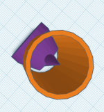
The big challenge I have currently is that when I use the BIB calculator to determine the driver location along the line, it returns a result of Zdriver approximately 21% of the line length from the tapered end. For all the designs I have looked at that obviously means the driver needs to interface with the cone in the middle and not with the outer cavity. As the ID of the cone tends to be fairly small at this point (vs the dimensions of the driver) I am having to create a taper on the back of the driver box. The attached picture shows the driver box interfacing with the cone (FYI the blue grid is actually to scale in mm). The box is initially flared out from the driver and then has a short parallel section before tapering back to meet the ID of the cone. My thinking here was to keep the resultant angle between the 2 tapered surfaces going back to the cone to be less than 90 degrees, my rationale being with 90 degrees or more you could easily get reflections bouncing off 2x 45+ degrees angles and return the resultant energy forward. Also keep in mind that this taper is actually a cone in reality. Again, let me repeat, I have no technical basis for this other than feel.
I did consider whether I could change the design to effectively curve the cone towards the driver where the 2 intersect as well as flatten it as much as possible to allow the driver box to have as little taper as possible and connect directly into the cone. Honestly the thought of managing the geometry behind curving and flattening the cone while maintaining the line length and parabolic (not linear as you guys pointed out) expansion is pretty hard to take on. But in theory I think it could be approximated fairly well by just calculating the "ideal" cross-sectional area at multiple points along the length of the hypothetically perfect cone and ensuring that along the length of the resultant shape that the equivalent actual point is the same cross-sectional area. In theory if the design challenge can be overcome the production is no more difficult for a complex shape than a relatively simple one.
The other challenge that has cropped up is the scale of my initial design. When I started prepping some of the 3D printed components the software was telling me it would be 5-6 days of printing for each component. With each speaker made up of 7-8 components that is a long time to print something if the result is rubbish. To that end I have actually started designing a much smaller version based on the Dayton Audio DMA80-8 3" driver. Putting that in the calculator yields a line length of 69" with a terminus diameter of 4.45" which means I can build based on a 4" PVC pipe. I think I can knock this concept together fairly cheaply and see if the whole concept is a disaster or not. The smaller design still has all the same technical challenges to overcome, so should in theory be a decent test before committing to a huge cost for the bigger version based on the FE168e∑.
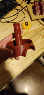
Lastly, just to show a little progress beyond concept, a friend of mine who is a whiz at 3D printing, and has some pretty fancy gear, printed one of my concept components at 30% scale to ensure that he shape was "printable". The results were pretty good in my opinion.
Once again, thanks everyone for reading and I really appreciate all the input and feedback. I have really enjoyed the design process so far (albeit based on aesthetics over technical data) but I am keen to learn more and also willing to face up to the fact that everything I have created to date both in concept and execution is potentially worthy of nothing more than the trash heap. I also apologize as I know I am definitely mixing a bunch of terminologies that probably simple do not apply that may be adding further confusion into the mix.
If anyone wants more details on my thoughts, or can spot any absolute no-no's, or has any ideas to throw out that I'm not thinking of yet, please feel free to jump in.
Thanks again,
Phil
Let me start by reiterating I have no background in speaker design theory and almost no technical understanding other than throw together a few different design elements to try and make something "cool".
Having said that, I have attached a very rough sketch of what I conceived to be the overall concept in my head. Proportionally the end result will be much taller and narrower than shown but I wanted to just rough it to show the concept. The FE168e∑ design yielded an OD of the outer pipe at 10.75" with a total speaker height of about 70".
The link to the Metronome page was actually very helpful. If you look at the "Conehead" pic what I am attempting to do is take the top part of the cone (above the blue line) and fold it back into the lower section. In my head this was very similar to the BIB which essentially takes a Voigt pipe shape and folds it in the middle to condense the overall dimensions (I know its technically definitely not that, but design-wise that's what I see when I look at the shapes involved.
Then other major difference to the conehead is rather than porting, I have essentially flipped the whole thing over and left the end of the Pipe open at it's terminus (same concept as the BIB).
Great pickup on the non linear expansion. You guys are absolutely right. Totally missed that. Glad to hear it shouldn't be too much of an issue.
The big challenge I have currently is that when I use the BIB calculator to determine the driver location along the line, it returns a result of Zdriver approximately 21% of the line length from the tapered end. For all the designs I have looked at that obviously means the driver needs to interface with the cone in the middle and not with the outer cavity. As the ID of the cone tends to be fairly small at this point (vs the dimensions of the driver) I am having to create a taper on the back of the driver box. The attached picture shows the driver box interfacing with the cone (FYI the blue grid is actually to scale in mm). The box is initially flared out from the driver and then has a short parallel section before tapering back to meet the ID of the cone. My thinking here was to keep the resultant angle between the 2 tapered surfaces going back to the cone to be less than 90 degrees, my rationale being with 90 degrees or more you could easily get reflections bouncing off 2x 45+ degrees angles and return the resultant energy forward. Also keep in mind that this taper is actually a cone in reality. Again, let me repeat, I have no technical basis for this other than feel.
I did consider whether I could change the design to effectively curve the cone towards the driver where the 2 intersect as well as flatten it as much as possible to allow the driver box to have as little taper as possible and connect directly into the cone. Honestly the thought of managing the geometry behind curving and flattening the cone while maintaining the line length and parabolic (not linear as you guys pointed out) expansion is pretty hard to take on. But in theory I think it could be approximated fairly well by just calculating the "ideal" cross-sectional area at multiple points along the length of the hypothetically perfect cone and ensuring that along the length of the resultant shape that the equivalent actual point is the same cross-sectional area. In theory if the design challenge can be overcome the production is no more difficult for a complex shape than a relatively simple one.
The other challenge that has cropped up is the scale of my initial design. When I started prepping some of the 3D printed components the software was telling me it would be 5-6 days of printing for each component. With each speaker made up of 7-8 components that is a long time to print something if the result is rubbish. To that end I have actually started designing a much smaller version based on the Dayton Audio DMA80-8 3" driver. Putting that in the calculator yields a line length of 69" with a terminus diameter of 4.45" which means I can build based on a 4" PVC pipe. I think I can knock this concept together fairly cheaply and see if the whole concept is a disaster or not. The smaller design still has all the same technical challenges to overcome, so should in theory be a decent test before committing to a huge cost for the bigger version based on the FE168e∑.
Lastly, just to show a little progress beyond concept, a friend of mine who is a whiz at 3D printing, and has some pretty fancy gear, printed one of my concept components at 30% scale to ensure that he shape was "printable". The results were pretty good in my opinion.
Once again, thanks everyone for reading and I really appreciate all the input and feedback. I have really enjoyed the design process so far (albeit based on aesthetics over technical data) but I am keen to learn more and also willing to face up to the fact that everything I have created to date both in concept and execution is potentially worthy of nothing more than the trash heap. I also apologize as I know I am definitely mixing a bunch of terminologies that probably simple do not apply that may be adding further confusion into the mix.
If anyone wants more details on my thoughts, or can spot any absolute no-no's, or has any ideas to throw out that I'm not thinking of yet, please feel free to jump in.
Thanks again,
Phil
Attachments
Somewhere i have a very similiar drawing.
...or more you could easily get reflections bouncing off 2x 45+ degrees angles...
At the wavelengths involved there is no reflection. Deflectors at the folds are counter-productive.
The intrusion of the coupler from the outside to the inside will reduce the cross-section of the outer-pipe as well as the little tunnel acts as a stub and i suspect impact the performance. Since the pipe is going to be 3D printed why not run one side of the inner pipe along one of the walls of the outer pipe. This will alos make it structurally more solid.
There is also a 2nd potential tap-in point for the driver (GM?).
dave
Yeah, the intersecting of the pipe is a big no no.
You are basically creating a band pass filter.
The upper part of the inner taper is basically going to be invisible to the sound. It’s way too thin. Something that in itself might be ok, but combined with the constriction just below, it’s not good.
3D printing the flange is a good idea. But there is a number of ways to do a better job (damping and structurally) by hand, if you have some simple tools and a little time.
Using a plastic or cardboard tube as the outside for a speaker, is quite an old idea. Going back to at least the 60s, quite possibly earlier, with many examples and much inspiration to draw from.
I remember one project that had the inner tube cut at an angle, lengthwise and glued to the inner wall of the big one.
That resulted in in crescent moon shaped cross section. This might be beneficial for absorbing the high frequencies without too much stuffing
Are you even sure you need the fold?
Depending on your ceiling height and driver, a long tube going floor to a few inches below the ceiling and the driver at ear height might be perfect.
The taper (sonically), and perhaps adjustment of the termination point of the pipe, could be done with sand bags (which would also give a nice low center of gravity, and provide damping) stuffing and holes drilled in the wall at the end of the pipe .
Last edited:
OP imo for what it's worth maybe try and do a regular BIB mock up first and then decide from there. Your concept is interesting and very worthy to try.. Perhaps having listened to a reg cab BIB for a reference you could build off that knowledge so to speak .. In any case cool idea and have at it!
Evening All
Thanks again for the feedback. Couple of answers to specific questions/comments raised.
Absolutely. I actually accounted for this in my original concept by increasing the overall diameter of the outer pipe in the section where the driver box was located. I had to google how to calculate the area of a segment of a circle (long time since my school days) but was able to find the overall increase in ID was not actually that much to account for the area being consumed by the driver box. I then used an approximation to curve the ID back to the point where the driver box finished. You can see the effect as a bunch of circles if you look at the bottom view of the driver box in my original post.
Nope, not sure at all. The only thing I have guiding my choices on line length was the BIB calculator spreadsheet. I do like the idea of linking the line length to the fundamental resonance frequency of the driver as it "makes sense" to me, but have no grounding in the science to know if it could be longer or shorter.
Based on the feedback and an attempt to read to Martin King's Quarter Wave Speaker Design info (of which I would say I probably comprehended a good 30%) I have come up with the following changes to iterate the design.
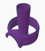
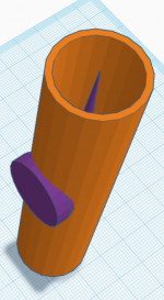
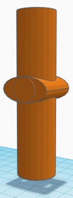
Remove the taper from the back of the driver box. Project rear of driver box to cross entire diameter of outer pipe. The thinking here was based on looking at some of the back loaded horn designs which have a driver box with a relatively small transition (cross-sectional area wise) into a horn (or in some cases a TL). By running my cone through the middle of the driver box what I effectively end up with is a expanding open TL (not expanding to horn proportions) from the bottom of the driver box, and a short closed tapered TL from the top. I did note the comment that the short line is probably not doing a lot sonically. The primary reason for keeping it is to provide the taper effect in the top section of the outer pipe (and I've grown to like it from an aesthetics perspective).
The thing this does do is require a much more aggressive flare of the outer pipe around the driver box to maintain the cross-sectional area of the outer pipe at this point in the line. That again should be fairly easy to design with a little geometry tinkering and CAD work.
I have attached a couple of pics of what I think this could look like. The flare in particular will need a lot of work and I think could end up looking much more spherical in nature. Will need to run some number of cross-sectinoal area consumed by the driver box.
Couple of questions/thoughts:
1) If using this driver box approach (as employed in BLH design) is there any guidance around box volume or minimum dimensions of the box?
I've looked at lots of designs and some of the driver boxes are quite small with the rear panels being very close to the back of the driver, but can't see anything to provide guidance on size.
2) What is the best shape for the back of the driver box?
Most obvious choices would be completely flat or following the curve of the outer pipe. But given this piece will be 3D printed I could do something more exotic. Perhaps a saw tooth deflector (something I have seen in some BLH) or an egg crate style. I could even open it to the rear and simply have an open stuffed tube (like the LX mini driver pipe). I guess the goal here is dispersion or absorption of the back wave. Perhaps this is something I could make a few designs and experiment (once the main concept has been proven).
I really appreciate the feedback from the community. There have been a few posts suggesting attempting to build something simple and go from there. I appreciate the approach, but honestly I am really enjoying the thought process of attempting to identify and mitigate the design flaws. I am an engineer by trade who has long been in a management role and I am finding the learning and design process really invigorating.
I also really appreciate some of the suggestions for different designs. I do like the idea of running the "inner" pipe down the side of the "outer" pipe. I am still hooked on the symmetry of the free hanging cone at the moment so not quite ready to give up on that one just yet.
Once again I appreciate all input. It's been a really enjoyable few weeks bringing these ideas together. But again, if anyone can see major flaws please let me know.
Thanks again for the feedback. Couple of answers to specific questions/comments raised.
The intrusion of the coupler from the outside to the inside will reduce the cross-section of the outer-pipe...
Absolutely. I actually accounted for this in my original concept by increasing the overall diameter of the outer pipe in the section where the driver box was located. I had to google how to calculate the area of a segment of a circle (long time since my school days) but was able to find the overall increase in ID was not actually that much to account for the area being consumed by the driver box. I then used an approximation to curve the ID back to the point where the driver box finished. You can see the effect as a bunch of circles if you look at the bottom view of the driver box in my original post.
Are you even sure you need the fold?
Nope, not sure at all. The only thing I have guiding my choices on line length was the BIB calculator spreadsheet. I do like the idea of linking the line length to the fundamental resonance frequency of the driver as it "makes sense" to me, but have no grounding in the science to know if it could be longer or shorter.
Based on the feedback and an attempt to read to Martin King's Quarter Wave Speaker Design info (of which I would say I probably comprehended a good 30%) I have come up with the following changes to iterate the design.
Remove the taper from the back of the driver box. Project rear of driver box to cross entire diameter of outer pipe. The thinking here was based on looking at some of the back loaded horn designs which have a driver box with a relatively small transition (cross-sectional area wise) into a horn (or in some cases a TL). By running my cone through the middle of the driver box what I effectively end up with is a expanding open TL (not expanding to horn proportions) from the bottom of the driver box, and a short closed tapered TL from the top. I did note the comment that the short line is probably not doing a lot sonically. The primary reason for keeping it is to provide the taper effect in the top section of the outer pipe (and I've grown to like it from an aesthetics perspective).
The thing this does do is require a much more aggressive flare of the outer pipe around the driver box to maintain the cross-sectional area of the outer pipe at this point in the line. That again should be fairly easy to design with a little geometry tinkering and CAD work.
I have attached a couple of pics of what I think this could look like. The flare in particular will need a lot of work and I think could end up looking much more spherical in nature. Will need to run some number of cross-sectinoal area consumed by the driver box.
Couple of questions/thoughts:
1) If using this driver box approach (as employed in BLH design) is there any guidance around box volume or minimum dimensions of the box?
I've looked at lots of designs and some of the driver boxes are quite small with the rear panels being very close to the back of the driver, but can't see anything to provide guidance on size.
2) What is the best shape for the back of the driver box?
Most obvious choices would be completely flat or following the curve of the outer pipe. But given this piece will be 3D printed I could do something more exotic. Perhaps a saw tooth deflector (something I have seen in some BLH) or an egg crate style. I could even open it to the rear and simply have an open stuffed tube (like the LX mini driver pipe). I guess the goal here is dispersion or absorption of the back wave. Perhaps this is something I could make a few designs and experiment (once the main concept has been proven).
I really appreciate the feedback from the community. There have been a few posts suggesting attempting to build something simple and go from there. I appreciate the approach, but honestly I am really enjoying the thought process of attempting to identify and mitigate the design flaws. I am an engineer by trade who has long been in a management role and I am finding the learning and design process really invigorating.
I also really appreciate some of the suggestions for different designs. I do like the idea of running the "inner" pipe down the side of the "outer" pipe. I am still hooked on the symmetry of the free hanging cone at the moment so not quite ready to give up on that one just yet.
Once again I appreciate all input. It's been a really enjoyable few weeks bringing these ideas together. But again, if anyone can see major flaws please let me know.
Attachments
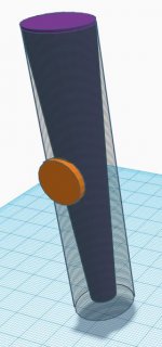
You mean like this?
I laughed when I first read your comment but I think you might actually be right.
The only challenge I can see is that at the Zdriver distance from the top there would only be about 6.5mm between the ID of the outer pipe and the OD of the inner cone (based on some quick rough calcs). So I would need to build the driver out from the pipe a bit.
Need to think about that one some more.
Attachments
Evening All
Apologies for the lack of updates on this thread. Long story short, the BIB Pipe project is on hold for the moment. It has been a very hectic summer which included moving house which not only slowed down my progress but also created some new priorities for solutions.
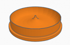
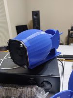
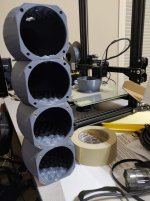
The good news is I have been working away on a 3D printed speaker solution which I intend to create a new thread for, but which is also giving me a ton of experience in 3D design and printing techniques.
Not wanting to be the guy with a ton of ideas that never follows through, I thought I would hold off on creating a new thread until I had some progress to show.
Attached are a couple of pictures of what I have going on. Once I get done with this project, I plan to return to the BIB pipe design and apply some of my learning. Plus I have about 2 months worth of 3D printing to complete this project so may get a bit bored.
I didn't get any significant testing done before the move, but did find some alternate candidates for cheap outer pipe material by using Sonotube (a concrete forming cardboard tube) which I believe has been used by some in the community in subwoofer type applications. I think this could provide a cheaper solution, particularly for larger diameter pipes.
Thanks for the interest and I will be sure to get back to this one once I get done with the other project.
Apologies for the lack of updates on this thread. Long story short, the BIB Pipe project is on hold for the moment. It has been a very hectic summer which included moving house which not only slowed down my progress but also created some new priorities for solutions.
The good news is I have been working away on a 3D printed speaker solution which I intend to create a new thread for, but which is also giving me a ton of experience in 3D design and printing techniques.
Not wanting to be the guy with a ton of ideas that never follows through, I thought I would hold off on creating a new thread until I had some progress to show.
Attached are a couple of pictures of what I have going on. Once I get done with this project, I plan to return to the BIB pipe design and apply some of my learning. Plus I have about 2 months worth of 3D printing to complete this project so may get a bit bored.
I didn't get any significant testing done before the move, but did find some alternate candidates for cheap outer pipe material by using Sonotube (a concrete forming cardboard tube) which I believe has been used by some in the community in subwoofer type applications. I think this could provide a cheaper solution, particularly for larger diameter pipes.
Thanks for the interest and I will be sure to get back to this one once I get done with the other project.
Attachments
...but did find some alternate candidates for cheap outer pipe material by using Sonotube...
Many projects have been based on pipe. Sonotube does not like people using their brandname for generic purposes :^) There are lots of sizes and brands of cardboard concrete pipe forms. They work well. PVC pipe is better but, unless you can score a free surplus bit, is pricier.
Laying Pipe with Audio Lego
the toobs Mk 1
toobz woofer
dave
- Status
- This old topic is closed. If you want to reopen this topic, contact a moderator using the "Report Post" button.
- Home
- Loudspeakers
- Full Range
- The BIB Pipe Project - Advice Needed