Hello - I'm wondering if someone can help me with some advice.
I have a Musical Fidelity A370 Mk1 that I have had from new - it hasn't had any work done on it. I mothballed it a while back as a refurb project because of strange noises (even stranger than usual) through the speakers after switch off and unpleasant hot smells (which I now think were due to dust).
I've opened the amp up and found the forum here where there seems to be some good knowledge about the amp, especially https://www.diyaudio.com/forums/solid-state/139711-musical-fidelity-a370.html.
My plan is to replace the big power supply electrolytic caps (following the advice on the A370 thread) but I have a couple of questions. I am a (digital) electronics engineer so have a reasonable range of test equipment.
1) The amp boards have a number of electrolytics caps on them. Electrolytics in seem to have relatively short lives compared to other component types so should I replace all of these?
2) In the A370 thread Don / AMV8 and Jez talk about adjusting the bias. There is a 100K preset pot on the amp boards which I guess is the bias adjust but I don't want to randomly turn the pot, presumably there is something I can measure. How do I set the pot 'correctly'?
Many thanks to anyone who can help
I am talking of that one file NOT the whole website as otherwise I would be blocked from reaching it .
It showed all the technical signs of an information gatherer and malware down-loader collector of your personal info .
I use several types of protection for my two browsers but this time it was Malwarebytes who got in first and that's one company I trust and so do many Americans.
I did not spent time investigating it as I was (obviously ) posting here.
You are at liberty to ignore my warning .
Thanks MultiMark for the advice on the caps. I figured I should replace them but it means removing the amp board (more specifically all those lovely FETs...) from the heatsink - I shouldn't be so lazy!
Thanks too to duncan2 for the warning about the service manual on the eserviceinfo website, I'll avoid that.
Which leaves the question about adjusting the bias / 100K pot, there must be something to measure to know how to set it...
Thanks too to duncan2 for the warning about the service manual on the eserviceinfo website, I'll avoid that.
Which leaves the question about adjusting the bias / 100K pot, there must be something to measure to know how to set it...
I had no problem with the download from eservice - noting that it's an RAR, not a PDF and you need a reader program for it. Otherwise you may well find that you get sent to a 3rd party site that is full of scams and gremlins, in order to find a free RAR program download.......Which leaves the question about adjusting the bias / 100K pot, there must be something to measure to know how to set it...
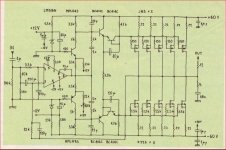
What's there is just a hand drawn schematic, much the same as any other MF design of the era, with an LM318 input stage followed by a discrete BJT VAS and 5 pairs of complementary Hitachi lateral mosfets (obsolete H-PAK plastic types 2SJ83/2SK227)
The solitary adjustment pot appears to control DC offset rather than bias and considering the high current of class A operation, it would be smart not to have that amount of current adjustable.
Attachments
I had no problem with the download from eservice - noting that it's an RAR, not a PDF and you need a reader program for it. Otherwise you may well find that you get sent to a 3rd party site that is full of scams and gremlins, in order to find a free RAR program download.
What's there is just a hand drawn schematic, much the same as any other MF design of the era, with an LM318 input stage followed by a discrete BJT VAS and 5 pairs of complementary Hitachi lateral mosfets (obsolete H-PAK plastic types 2SJ83/2SK227)
The solitary adjustment pot appears to control DC offset rather than bias and considering the high current of class A operation, it would be smart not to have that amount of current adjustable.
The adjustment pot is for the bias, I built a P170 clone some time ago and recently a discrete version of the circuit. The P170 just does not have the driver transistors as the gate source capacitance can easily be driven from the op amp as it’s only a single pair of lateral FETS on the output stage.
I stand corrected if that is in fact a bias pot. but how would offset be adjusted, if not by swapping components in the production line? Then it probably also requires the same parts swapping process whenever semi replacements are necessary.
A class AB amplifier certainly needs bias adjust but I would have thought it unnecessary for class A, where fixed resistors are generally fine, cheaper and superior for reliabilty. If it's only a partial class A or high bias class AB design, it becomes arguable whether bias adjustment is a wise inclusion or not because there is a likelihood of overheating and serious damage in the hands of unwise tweakers.
A class AB amplifier certainly needs bias adjust but I would have thought it unnecessary for class A, where fixed resistors are generally fine, cheaper and superior for reliabilty. If it's only a partial class A or high bias class AB design, it becomes arguable whether bias adjustment is a wise inclusion or not because there is a likelihood of overheating and serious damage in the hands of unwise tweakers.
While I cannot fault your engineering logic in your second paragraph it is a fact of life that there are many class "A" power amplifier designs that include adjustment with or without the use of a BJT .
Heat has to come into consideration as does the size of the analogue power supply.
As JLH has pointed out many people make use of a portion of full class A say- 5W -10W then sliding (smoothly in a good design) into AB.
If the customer lives in a suburban setting with neighbours even 10W pure class A is bound to attract the attention of the police.
Cost certainly enters into it for the general public ,class A is always dearer but the attraction of an amplifier to the public which is cheap but advertises "class A " but is really limited does sell equipment .
On the other hand--
you live in the "Outback " in isolation and are well off then a very large ,heat inducing piece of equipment is just the job, that is if the "other half " allows it in the living room.
I repeat I am NOT questioning your engineering logic just saying "horses for courses ".
Quite so and no problem with questioning. For starters, small class A designs like JLH's 1969 design and some of Sugden's commercial offerings can certainly be adjusted from modest levels to full class A bias.
However, if I were concerned at all about the effect of DC at the output of a balanced rail supply amplifier, I'd hope for either a blocking cap, DC servo (nulling circuit) or adjustment pot. to reduce it with certainty to <50 mV. I wouldn't trust the 5% tolerance carbon resistors in Sugden's early designs, for example, to achieve that without trimming.
For interest, MF products arrived in Oz back in the 1980s, with a splash of retail promotion and loads of models to choose from, busy shops and brisk sales, even here in my current location, hundreds of km from capital cities. They left a trail of failures behind them though - just not designed with enough tolerance to higher ambient temperatures, nor with appropriate component ratings for safety and reliabiity.
They returned in more recent times with the high end A series and I wound up with a shop demo A5 model CD player - promising much at $4k but failing to read any disc at all after some 40 plays. They were credited with using trivista valves in the line amplifiers but even they couldn't save the day for this fragile and by comparison with contemporary Japanese brands, poorly engineered piece of work. It did sound OK if rather dry, but other models with 24 bit DACs at far lower prices sounded quite OK too.
Interesting Ian this is just the type of conversation I enjoy --interaction on a technical level.
Never owned MF equipment but I see its now owned by an Austrian company -Audio Tuning-2018 .
I remember the A1 amplifier got a good write up by UK "golden ears " at the time.
Antony wasn't a enthusiast of exotic cables and neither is D.Self who used a ring main electric cable in EW to prove his point.
Certainly caused some arguments there ,a lot of the fire has gone out of EW now I enjoyed the arguments in the Letters section.
Change of editor.
I stand corrected if that is in fact a bias pot. but how would offset be adjusted, if not by swapping components in the production line? Then it probably also requires the same parts swapping process whenever semi replacements are necessary.
A class AB amplifier certainly needs bias adjust but I would have thought it unnecessary for class A, where fixed resistors are generally fine, cheaper and superior for reliabilty. If it's only a partial class A or high bias class AB design, it becomes arguable whether bias adjustment is a wise inclusion or not because there is a likelihood of overheating and serious damage in the hands of unwise tweakers.
Think of it as a boosted output op-amp, the op determines the offset, which in terms of the input bias currents, offset voltages and feedback resistor values adds to to the grand total of sweet FA.
Hi Nigel
I have exactly such a biest sitting around me, i think it works flawless and never made any problems. Thanks to Ian Finch fpr the schematics.
It drove some Acoustats before.
I think abouth selling it, but no iedea what ist is worth.
I think it sounds pretty good, but i am no MuFi Freak.
What do you think its worth to invest?
Thanks to everyone for the posts - there is a lot of good and interesting stuff here.
Can I get back to an earlier question: there is a pot on the amplifier PCB, can anyone provide any guidelines on adjusting it appropriately? I presume I should put a meter or a scope somewhere on the circuit and measure something whilst adjusting the pot.
I decided to download the manual from eserviceinfo using a heavily protected computer - I did get warnings but at the end of the day got a rar file with a picture of the board mounted on heatsink and the hand-drawn schematic but nothing about setting it up.
Any help really appreciated!
Yes, that's all there was at the site. The pic. looked hopeless for any reference use. To the matter, bias is measured (calculated actually) by measuring the DC voltage drop across any resistor in series with this current. i.e use Ohm's law, I=E/R with any sort of calculator if you need to. Suitable series resistors for testing bias are the 10 x 0R22 cement types connected to each power Mosfet source pin.
There is a problem though, as there are 5 parallel complementary pairs of Mosfets, each Mosfet with its own source resistor. So there are 5 parallel currents to determine and add up before you arrive at a total bias current. Or you could assume that the currents are approximately equal and determine the current through one resistor in a pair and multiply it by 5. This is probably more than adequate accuracy for Mosfet bias setting but check the other 4 pairs too and select a median current pair for more precision if you wish.
Regarding Mosfet bias, let's be realistic. Unlike BJTs, the bias current is arbitrary and the more the merrier for lowest distortion, virtually up to max. current capacity but that's only possible with a massive power supply and cooling system. The limitations here are the small heatsinks and transformer so if you increase the bias for some reason, you must be able to dissipate the corresponding increased heat. With MFs notoriety for overheating, I wouldn't choose to do it but by all means measure what you have and compare total currents for each channel. I would not expect even 10% bias difference to make any audible difference, t.b.h.
MF must have made a decision to use the arrangement they did based on temperature, I'd suggest. So you'll need to determine what the factory setting was and how it was set during production to ensure you don't overheat and cook the amp. or underbias it such that sound quality deteriorates noticeably.
Personally, I would not touch what you have unless there has clearly been some alteration or significant change since new. Old amps deteriorate with years of heat cycling and adjustment pots are cheaply made, particularly fragile components, so take care if you must make adjustments.
I meant to describe the source resistors above as wire-wound though they are still coated with cement-like high temp. insulation. Note that actual component values used were often different to the spec. and different from the schematic, batch to batch. (That's MF for you) They are the green tubular resistors shown above or below each power mosfet in this preview - click on for a larger image: Heres the amp board, the short lifespan... - Audio Tech Service Network | Facebook
Hi Nigel
I have exactly such a biest sitting around me, i think it works flawless and never made any problems. Thanks to Ian Finch fpr the schematics.
It drove some Acoustats before.
I think abouth selling it, but no iedea what ist is worth.
I think it sounds pretty good, but i am no MuFi Freak.
What do you think its worth to invest?
Hi Groove T,
I think it's tricky with old amps like this, for example you know the electrolytic caps will degrade with time and will need replacing.
I'm hovering on the edge of not doing this but I will because it's a lovely amp when everything is working and I've had it from new.
What do I think its worth to invest? Haven't a clue!
- Status
- This old topic is closed. If you want to reopen this topic, contact a moderator using the "Report Post" button.
- Home
- Amplifiers
- Solid State
- Musical Fidelity A370 refubr