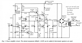
A few years back, I built this amplifier, as described in the article of the Wireless World magazine in July 1970. The schematic is shown in the left picture. My modifications concerned a regulated split power supply and the use of 2N3055H and MJ2955 as output transistors.
Also I used the components values for the 8 Ω load as shown in the article.
I was very pleased with the technical and acoustical performance of the amplifier.
The only "problem" I found was when the load was less than 8 Ω. In this case the maximum voltage output was very different for the positive and negative side of the signal.
Recently, I needed a low power amplifier to drive a 4 Ω loudspeaker and I decided to look again at this amplifier and modify it so that it could drive a 4 Ω load. My intension was to perform as little changes as possible.
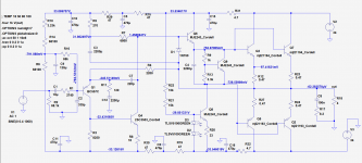
The right figure shows the schematic of the modified amplifier which was also extensively simulated in LTSpice.
Any comments or suggestions for improvements are welcome.
Also I used the components values for the 8 Ω load as shown in the article.
I was very pleased with the technical and acoustical performance of the amplifier.
The only "problem" I found was when the load was less than 8 Ω. In this case the maximum voltage output was very different for the positive and negative side of the signal.
Recently, I needed a low power amplifier to drive a 4 Ω loudspeaker and I decided to look again at this amplifier and modify it so that it could drive a 4 Ω load. My intension was to perform as little changes as possible.
The right figure shows the schematic of the modified amplifier which was also extensively simulated in LTSpice.
Any comments or suggestions for improvements are welcome.
Attachments
The reason this circuit performs poorly under low-Z load is that there is only one EF stage on the negative side, and you have not changed that feature??? If you want to use the same PCB, perhaps you should consider using Darlington power transistors. This will allow you to take the heat off Q6 and Q8, and regain ~3 Volts of output swing wasted in Q8. Note that any active current source uses some voltage swing compared to the original bootstrap. Many of the best amps use 3 stages of EF. Be sure to cross-couple the drivers if you add EF stages.
The original circuit was primarily designed for 16 ohms speakers which were more commonly used back in the day.
The modified resistor values originally given are for 8 ohms speakers/load.
For 4 ohms my "guess" would be R1 = R2 = 0.22R R3= 270R R4 = 47R, and re-set current (using the 100R pot) for:
200mA (320mW will be in class A)
400mA (for 640mW in class A)
Heatsinks should settle at less than 60 degrees max for safety if on outside of case and touchable.
you can do 15-20 degrees more if they are inside a well ventilated case and not directly touchable.
With the resistor values thus changed there should not be any need to modify the negative side EF stage.
This information is given as guidance only and has not been tested!
Simon
Last edited:
It seems to me that this kind of circuits aren't suitable for split power supplies, as the DC offset at the output can't be accurately fixed to 0V. Also, 1.5Ω in the emiters are too high to drive 4Ω loads, you are loosing about 40% of the output swing there.
I would try another better configuration, IMHO.
I would try another better configuration, IMHO.
I'm thinking... replace the output pair with lateral FET's. That would overcome the limitation of the driver stage and laterals should also be stable in bias current with the simple bias scheme this amp has.
If you really want to go dual rail then add a simple servo.
If you really want to go dual rail then add a simple servo.
What do you mean the amp at the left is a quad 303
Trev
It’s the successor of the Quad II tube amp and was Peter Walkers first transistor amp back in the early seventies.
Hans
The new design has a lot of volts wasted in the current sink load using two green LEDs in series. Lose one of the LEDs and reduce the resistor accordingly perhaps? This should lead to more symmetrical clipping (which is one of the stated goals).
You have no high frequency decoupling on the PSU rails.
You have no high frequency decoupling on the PSU rails.
The amp at the left is the Quad 303
The amplifier at the left is the one that J. Linsley Hood describes in the Wireless World, July 1970, article. I don't think it is the Quad.
It’s the successor of the Quad II tube amp and was Peter Walkers first transistor amp back in the early seventies.
Hans
The circuit in question is definitely that by JLH in published in Wireless World in 1970.
At one time I had that issue in my possession. The additional diode modification to the standard quasi complementary output stage (later recast in form by Baxandall) appeared in a letter from I.M.Shaw in the same issue of that magazine.
Initially I was not attracted by the use of bootstrap connections and the unbalanced look of Linsley-Hood's circuit. This and the preceding introductory article gave rise to a series of challenging letters to the editor and the idea never caught on.
It was recently reported that the latest Rega amplifiers incorporate some of Linsley-Hood's output stage thinking so it is remarkable nearly 50 years on the thinking is not completely dead.
Linsley-Hood's original aim was to devise a circuit to rival the simple Class A circuit Hood had designed but without the penalty of the heat dissipation involved.
That is the context of my current interest since I have a 1996 Class A which has that issue. I will save my comments on the AB design for later.
The Quad 303 which succeeded the Quad II used a quasi complementary triple output stage.
The original circuit was primarily designed for 16 ohms speakers which were more commonly used back in the day.
The modified resistor values originally given are for 8 ohms speakers/load.
For 4 ohms my "guess" would be R1 = R2 = 0.22R R3= 270R R4 = 47R, and re-set current (using the 100R pot) for:
200mA (320mW will be in class A)
400mA (for 640mW in class A)
Heatsinks should settle at less than 60 degrees max for safety if on outside of case and touchable.
you can do 15-20 degrees more if they are inside a well ventilated case and not directly touchable.
With the resistor values thus changed there should not be any need to modify the negative side EF stage.
This information is given as guidance only and has not been tested!
Simon
I run a simulation with the values for R1, R2, R3, R4 you suggested. The maximum output of the amplifier was +15V and -9V peak. Not much better result.
The dc offset should follow the arrangement for the 1996 Class A circuit where a 7815 regulator was used with a resistor and trim-pot in series from the output connecting to the emitter of the input transistor. For simulation purposes just use a voltage block as for the power supply rails and label it 7815. In real life that will need capacitor to earth to stabilise the output but you don't need to show that in your simulation.
The value of the series resistor trim-pot combination will be a multiple of 10k
The value of the series resistor trim-pot combination will be a multiple of 10k
This amp ran very high bias currents in both the driver and outputs, which would mean it generated a lot of heat even undriven. This was probably necessary because the compensation is a very large cap that bypasses the output out of the feedback loop so any cross-over distortion is not controlled by the feedback.
Your simulation raises the total supply voltage from 47 to 68 Volts. This is contrary to the need for operation with lower impedance loads while maintaining the thermal dissipation. However the original high bias currents mean the dissipation was much higher than it need be so if you can reduce the bias current to more typical levels then heat may not be a problem. But I have to wonder why you changed the voltage unless you plan to change the power transformer?
Experienced DIYA would completely redesign the amplifier board to a modern circuit but even they might be tempted to just buy existing modules from Apex or China/Amazon. It depends on if you just want a working solution or do you want to "make it your own".
You can reuse the power transformer for a bipolar circuit by creating a ground voltage half way between the 47V + and -, ei make 23.5V ground and float the existing negative. This takes two big ecaps instead of one.
One more thing. Bootstrapping is a great way to maximize voltage swing.
I should repeat what Mooly and Mark said: MOSFETs would be a good way to correct the lack of output current and the two LEDs is wasteful of voltage. If you choose to continue with the 100mA driver current then I would replace the LEDs with small diodes (~1n4148) and replace the emitter resistor with about 6.8 Ohms. Using MOSFET outputs, 25mA driver current would be plenty.
Last edited:
> Your simulation raises the total supply voltage from 47 to 68 Volts. This is contrary to the need for operation with lower impedance loads
Exactly. A conversion from 16r to 4r at the same power suggests 24V, not 68V.
And cutting a lot of resistors to quarter-value.
Basically cutting a townhouse to a ranch house.
Exactly. A conversion from 16r to 4r at the same power suggests 24V, not 68V.
And cutting a lot of resistors to quarter-value.
Basically cutting a townhouse to a ranch house.
I am interested in assembling this amp. I have the required semis.(current replacements). Can some one help in finalizing the design, PCBs etc ?
Also, transformer, Caps, box and Heatsinks !
Also, transformer, Caps, box and Heatsinks !
- Status
- Not open for further replies.
- Home
- Amplifiers
- Solid State
- Modifications to the JLH 15-20W Class AB amplifier (1970)