Good day all
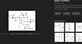
I have built this circuit as part of a little audio mixer.
Im getting a 200mV DC on the output pin. Opamp is not oscillating at all, actually perfectly clean DC.
I have tried different bipolar and JFET opamps.
This is a dual opamp and both sections have the same resistors.
I also tried a resistor on pins3/5. No difference.
Can anyone help? thanks!
Attachments
As drawn and with a common opamp (TL072, 4558 etc) then there should definitely be close to zero on the output.
The output should be at the same voltage as pin 3. The only exception is if the opamp isn't a FET type and the 47k resistor (make sure it really is 47k) is causing an error due to offset bias currents.
The output should be at the same voltage as pin 3. The only exception is if the opamp isn't a FET type and the 47k resistor (make sure it really is 47k) is causing an error due to offset bias currents.
Noise and thermal voltages are not DC
I never saw a thermocouple or thermopile giving AC voltages.
It is obvious that if he changed the opamp and the troubles persists, then the opamp is not responsible. Then, this reduces the problem in a 1 variable. There are two resistors, so no more things to test. Or thermal voltages/currents, or a small DC carried from the previous stage or, perhaps, a strong elecrtomagnetic field being rectified in the stage.
Osvaldo, there is no question where this comes from. As I said, EE 101. You can expect the offset to be rather large, because that is how opamp circuits work. You have an opamp with 4mV offset, you amplify it 50 times, you get 200mV. What is the question??
The question is, how do I change the circuit so it amplifies the signal and not the DC offset. I am not giving it away, it's really too simple. Google is your friend.
Jan
The question is, how do I change the circuit so it amplifies the signal and not the DC offset. I am not giving it away, it's really too simple. Google is your friend.
Jan
The offset is amplified almost 50 times. 4mV offset, not unreasonable, would give 200mV at the output.
Jan
I'm not convinced Jan
") Take the circuit as drawn and described.
Take the circuit as drawn and described.The 1k is not connected to anything. The opamp has no knowledge of that resistor.
With a FET opamp the offset should be close to zero.
This may be true for BJT input opamp but not for most JFET input under normal condictions: it is well know that JFET and MOSFET input opamps don't need equilibrium resistor in the grounded non inverting input.
You confuse input offset current with input offset voltage. A FET input opamp can have negligible input offset current, but will have |(generally larger) input offset voltage. Opamp circuits do what they do; if DC coupled at gain of 50, the offset will be 50 x input offset voltage, period.
Jan
..The 1k is not connected to anything. The opamp has no knowledge of that resistor...
Has OP revealed if the left-most dot is connected to anything?
As shown, it is unity gain for its own offset, so few-mV.
If the input is shoted to ground, or connected to an equivalent low-Z source, gain is 47 and 4mV offset becomes 200mV offset. (However many "4mV" opamps today run <1mV typical, and the opamp was changed with apparently identical result).
The clues are in the very first post/question.
50X gain, 1k input impedance, so we can expect a a standard low impedance microphone, so around 200 ohm DCR.
That input stage isn´t suitable for anything else, neither a Guitar, nor a Keyboard, line out, pedal out, etc. , so a dynamic microphone is practically self confirmed.
In this case offset seems to be voltage type, which affects both Bipolar and Fet input Op Amps; current caused offset is real, of course, but given the very low value input resistor, voltage drop across it will be very small too, that might explain the apparent same results with Bipolars and Fet type, and the apparent "no effect" of grounding pin 2 straight to ground or through a 1k resistor.
It is not that in both cases "there is no effect" but that variation is quite small.
The main solution lies in killing the 50X gain, turning it into 1X for DC, that implies adding a capacitor in series with input.
I suggest a 10uF electrolytic, 16 or 25V rating is fine, in theory a bipolar would be needed but in practice and given the feeble signal level a standard polarized one will work fine.
Sorry Jan for the spoilers
Given the values shown, it´s a simple Mic preamp.I have built this circuit as part of a little audio mixer.
Im getting a 200mV DC on the output pin[/B].
50X gain, 1k input impedance, so we can expect a a standard low impedance microphone, so around 200 ohm DCR.
That input stage isn´t suitable for anything else, neither a Guitar, nor a Keyboard, line out, pedal out, etc. , so a dynamic microphone is practically self confirmed.
All regular Op Amps have offset and 4mV is not an unusual value, by any means.I have tried different bipolar and JFET opamps.
This is a dual opamp and both sections have the same resistors.
I also tried a resistor on pins3/5. No difference.
In this case offset seems to be voltage type, which affects both Bipolar and Fet input Op Amps; current caused offset is real, of course, but given the very low value input resistor, voltage drop across it will be very small too, that might explain the apparent same results with Bipolars and Fet type, and the apparent "no effect" of grounding pin 2 straight to ground or through a 1k resistor.
It is not that in both cases "there is no effect" but that variation is quite small.
The main solution lies in killing the 50X gain, turning it into 1X for DC, that implies adding a capacitor in series with input.
I suggest a 10uF electrolytic, 16 or 25V rating is fine, in theory a bipolar would be needed but in practice and given the feeble signal level a standard polarized one will work fine.
Sorry Jan for the spoilers
Has OP revealed if the left-most dot is connected to anything?
Not that I'm aware.
As shown, it is unity gain for its own offset, so few-mV.
Yep.
If the input is shoted to ground, or connected to an equivalent low-Z source, gain is 47 and 4mV offset becomes 200mV offset. (However many "4mV" opamps today run <1mV typical, and the opamp was changed with apparently identical result)
That bit puzzled me as well. Swapping between common devices (the likes of TL072's 4558's 5532's etc should have shown differences.
Which ones? What were their input offset voltages?Good day all
I have built this circuit as part of a little audio mixer.
Im getting a 200mV DC on the output pin. Opamp is not oscillating at all, actually perfectly clean DC.
I have tried different bipolar and JFET opamps.
Opamps vary considerably in offset voltage, some are designed for DC precision where this is very important (10's of µV are possible), one's designed for audio don't optimize DC offset as its immaterial to AC signals (within reason), and several mV or even 10's of mV is not a show stopper.
If the source impedances are high, input bias currents become significant sources of offset too.
Just returning to this thread because tbh, curiosity got the better of me and although I can't disagree with the technical arguments, the answers just didn't sound right to what I would have expected in practice.
So... Sunday morning and a breadboard and two 9 volt batteries, one 47k and one 910 ohm(couldn't find a 1k with legs on) and lets see what the real world results are.
Two LF353's (FET) gave 0.00 mV and 0.9mV for the 'floating' input and -2.2mV and +51mV for the grounded 910 ohm.
An LM833 was -13.3mV open and +2.2mV with the 910 ohm.
A 4560 was -1mV open and +39mV with the 910 ohm.
A 5532 was +6.7mV open and -68mV with the 910 ohm.
A 1458 was +1mV and -68mV with the 510 ohm.
Finally a 4558 was -1.2mV and +20mV with the 910 ohm.
So... Sunday morning and a breadboard and two 9 volt batteries, one 47k and one 910 ohm(couldn't find a 1k with legs on
) and lets see what the real world results are.Two LF353's (FET) gave 0.00 mV and 0.9mV for the 'floating' input and -2.2mV and +51mV for the grounded 910 ohm.
An LM833 was -13.3mV open and +2.2mV with the 910 ohm.
A 4560 was -1mV open and +39mV with the 910 ohm.
A 5532 was +6.7mV open and -68mV with the 910 ohm.
A 1458 was +1mV and -68mV with the 510 ohm.
Finally a 4558 was -1.2mV and +20mV with the 910 ohm.
- Status
- This old topic is closed. If you want to reopen this topic, contact a moderator using the "Report Post" button.
- Home
- Source & Line
- Analog Line Level
- Why DC offset offset output.