Hello PSU gurus,
This is my first post to this portion of the forum. I am not a psu kinda guy, so wanted some input. I recently acquired the above dac for short money and wanted to play. Unfortunately, I no one has the schematic - not even Monster who made the stuff!
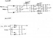
One of the things I'm hoping to do is a PSU mod. The current setup is an ite rated walwart putting out 16v ac. It plugs into the case via standard size N coax plug. Rectifying is done on board.
My problem with the current setup is that it takes the pin leg of the walwart to create the + and - for various portions of the circuit, and uses the shield leg for the ground. The + and - then goes to different sections, each with it's own regulator pair (lm7815 and lm7915 for example).
The pin leg goes to 2 diodes, one for + and one for -. It is therefore half-wave rectification which, to me is half-*** rectification causing larger ripple, etc.
I was thinking that I could 'tap' into the shield leg, with 2 more diodes to the + and - thereby creating full rectification (hmmm...the more I type out the word, the wierder it sounds ).
).
Would this be a some kind of problem as far as grounding, noise, etc.? Or should I get a ct tranformer, take the two legs through a bridge or 4 diodes for the + and -, and use the ct for the ground?
If it helps, I have attached a drawing of the current setup and my proposed setup. Sorry, I'm not up to snuff at drawing schematics.
Any help greatly appreciated!
Wayne
This is my first post to this portion of the forum. I am not a psu kinda guy, so wanted some input. I recently acquired the above dac for short money and wanted to play. Unfortunately, I no one has the schematic - not even Monster who made the stuff!
One of the things I'm hoping to do is a PSU mod. The current setup is an ite rated walwart putting out 16v ac. It plugs into the case via standard size N coax plug. Rectifying is done on board.
My problem with the current setup is that it takes the pin leg of the walwart to create the + and - for various portions of the circuit, and uses the shield leg for the ground. The + and - then goes to different sections, each with it's own regulator pair (lm7815 and lm7915 for example).
The pin leg goes to 2 diodes, one for + and one for -. It is therefore half-wave rectification which, to me is half-*** rectification causing larger ripple, etc.
I was thinking that I could 'tap' into the shield leg, with 2 more diodes to the + and - thereby creating full rectification (hmmm...the more I type out the word, the wierder it sounds
).Would this be a some kind of problem as far as grounding, noise, etc.? Or should I get a ct tranformer, take the two legs through a bridge or 4 diodes for the + and -, and use the ct for the ground?
If it helps, I have attached a drawing of the current setup and my proposed setup. Sorry, I'm not up to snuff at drawing schematics.
Any help greatly appreciated!
Wayne