A few years ago a few audiophile power supplies landed on my bench for testing. I've never published the results, so why not? It could be useful for someone...
These are old results and I no longer have the boards, so don't ask for more tests.
Let's start with the first candidate: GoldMiniReg aka "GOLD reference regulator". I think it's a commercial product. It has a golden PCB so it must sound good, and a huge TO-247 pass device, so baddass it doesn't even need a heatsink.

It is definitely a Jung SuperReg clone.

Lots of expensive and oversized parts:
MUR1520G OnSemi "15A 200V Ultrafast 35ns/60ns Recovery Time", with caps in parallel, but no snubber.
OPA134, J170, LM336
One silver mica cap, 9 film caps, probably to distract the eye from the "No Name Shenzen Special" electrolytics.
The pass device is a very chunky 2SC5200, NPN 230V 15A, max 150W (hum), probably one of the worst possible choices for this: high voltage device, therefore high Vcesat, but in a regulator you want to use it at low Vce, it has huge capacitance (especially at low Vce), very low fT (30MHz) that it only reaches at high current which won't be the case here, hFe is mehhhhh, etc.
Alright, it's a 5V regulator, I load it with 47 ohms (~100mA). Output ripple:

Huh?
I then discovered my XYTRONIC LF3000 soldering iron used PWM on its heater and apparently it puts out some noise. So it found a new use as a conducted EMI generator.
Measuring the input smoothing caps:

Yes, there is something (white arrow). I'm not talking about the rectifier spike and associated ringing which fills the whole screen due to no snubber, but about the tiny fur on the trace, that's the noise from the soldering iron. It doesn't look that bad...
Then I compared the amplitude of the noise on the input and the output of the regulator. It was higher on the output. Extraordinary.
An output impedance sweep with the network analyzer reveals the circuit has an impedance spike close to the frequency of the offending noise, around 300kHz, which means it is unstable. And it will probably amplify whatever noise it picks up, which explains the above.

I did more tests with the network analyzer output cable not connected to anything, the stripped end of the coax that I use to inject signal into stuff just lied there in the general vicinity of the regulator... and it managed to pick up 300kHz and reproduce it in the output 😀
An output impedance test with a 10µF MLCC capacitor in the output should be the final nail in this coffin.

Verdict: Failure.
These are old results and I no longer have the boards, so don't ask for more tests.
Let's start with the first candidate: GoldMiniReg aka "GOLD reference regulator". I think it's a commercial product. It has a golden PCB so it must sound good, and a huge TO-247 pass device, so baddass it doesn't even need a heatsink.
It is definitely a Jung SuperReg clone.
Lots of expensive and oversized parts:
MUR1520G OnSemi "15A 200V Ultrafast 35ns/60ns Recovery Time", with caps in parallel, but no snubber.
OPA134, J170, LM336
One silver mica cap, 9 film caps, probably to distract the eye from the "No Name Shenzen Special" electrolytics.
The pass device is a very chunky 2SC5200, NPN 230V 15A, max 150W (hum), probably one of the worst possible choices for this: high voltage device, therefore high Vcesat, but in a regulator you want to use it at low Vce, it has huge capacitance (especially at low Vce), very low fT (30MHz) that it only reaches at high current which won't be the case here, hFe is mehhhhh, etc.
Alright, it's a 5V regulator, I load it with 47 ohms (~100mA). Output ripple:
Huh?
I then discovered my XYTRONIC LF3000 soldering iron used PWM on its heater and apparently it puts out some noise. So it found a new use as a conducted EMI generator.
Measuring the input smoothing caps:
Yes, there is something (white arrow). I'm not talking about the rectifier spike and associated ringing which fills the whole screen due to no snubber, but about the tiny fur on the trace, that's the noise from the soldering iron. It doesn't look that bad...
Then I compared the amplitude of the noise on the input and the output of the regulator. It was higher on the output. Extraordinary.
An output impedance sweep with the network analyzer reveals the circuit has an impedance spike close to the frequency of the offending noise, around 300kHz, which means it is unstable. And it will probably amplify whatever noise it picks up, which explains the above.
I did more tests with the network analyzer output cable not connected to anything, the stripped end of the coax that I use to inject signal into stuff just lied there in the general vicinity of the regulator... and it managed to pick up 300kHz and reproduce it in the output 😀
An output impedance test with a 10µF MLCC capacitor in the output should be the final nail in this coffin.
Verdict: Failure.
Our next victim will be a "Salas Mini Shunt and USB isolator". This is most likely not designed by Mr. Salas himself, so I hope he will forgive me.

No comments on the layout.
The schematic is rather complicated. The FET pass device will have current-dependent transconductance, it's a huge slow FET and there is no source resistor, so stability versus output caps should be a lot more "conditional" depending on load current than with a simple BJT with emitter resistor. No problem if it works, but it should be checked.
The voltage reference is a LED, so there is no temperature compensation. Softly blowing some air on the circuit produces some quite substantial voltage variations...

Besides that, noise and ripple are alright, about 10µV, here with Samuel Gröner's x1000 preamp:

Note strong 100Hz noise modulation due to current-dependent MOSFET transconductance.
Since it is designed to be used with the USB isolator on the same PCB, and said USB isolator has 100nF MLCC on the input, I connect the output of the reg to the isolator, with 100nF ceramic cap. Wild oscillations happen.

This is the corresponding output impedance, with the cap.

This would be easily fixed by adding an electrolytic cap with some ESR on the isolator board, and using a higher MLCC value like 10µF. However, the board came this way and was supposed to be used this way, so I tested it this way.
Verdict: Failure.
No comments on the layout.
The schematic is rather complicated. The FET pass device will have current-dependent transconductance, it's a huge slow FET and there is no source resistor, so stability versus output caps should be a lot more "conditional" depending on load current than with a simple BJT with emitter resistor. No problem if it works, but it should be checked.
The voltage reference is a LED, so there is no temperature compensation. Softly blowing some air on the circuit produces some quite substantial voltage variations...
Besides that, noise and ripple are alright, about 10µV, here with Samuel Gröner's x1000 preamp:
Note strong 100Hz noise modulation due to current-dependent MOSFET transconductance.
Since it is designed to be used with the USB isolator on the same PCB, and said USB isolator has 100nF MLCC on the input, I connect the output of the reg to the isolator, with 100nF ceramic cap. Wild oscillations happen.
This is the corresponding output impedance, with the cap.
This would be easily fixed by adding an electrolytic cap with some ESR on the isolator board, and using a higher MLCC value like 10µF. However, the board came this way and was supposed to be used this way, so I tested it this way.
Verdict: Failure.
Attachments
The next volunteer is an extremely boring LM317 board by curryman. It is boring, because it works, so there is not a lot to rant about.

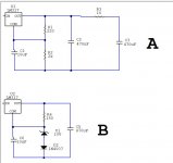
There is a snubber on the transformer secondary, so it's clean, no scope screenshot with ridiculous diode ringing. I'll post the schematic instead.

Output noise and ripple are what you would expect of a LM317, not worth taking a screenshot, it's clean. Note the LM317 rides on top of a zener so its internal reference noise and output impedance are not multiplied by the loop gain. This is a cost-effective trick.
Output impedance of 5V version, measured on load. Supply is connected to load with some wires and the load is a mockup "board" with 470µF Panasonic FR cap, plus a resistor for load current. It's clean and smooth, no ringing or peaks.

Same, with extra 10µF MLCC on the load side, no problem.

With just a 10µF MLCC on the load, it's a bit borderline. It would be cleaner if the output cap on the reg had say 0.2R ESR instead of 0.1R. But really, that's a problem with the load, it should really have a bulk electrolytic on it.

With an ultra low ESR polymer cap, it's pretty ugly, which is expected. You can't have a flat smooth impedance with polymer caps if there is wire inductance between the reg and the caps.

Verdict: Success.
There is a snubber on the transformer secondary, so it's clean, no scope screenshot with ridiculous diode ringing. I'll post the schematic instead.
Output noise and ripple are what you would expect of a LM317, not worth taking a screenshot, it's clean. Note the LM317 rides on top of a zener so its internal reference noise and output impedance are not multiplied by the loop gain. This is a cost-effective trick.
Output impedance of 5V version, measured on load. Supply is connected to load with some wires and the load is a mockup "board" with 470µF Panasonic FR cap, plus a resistor for load current. It's clean and smooth, no ringing or peaks.
Same, with extra 10µF MLCC on the load side, no problem.
With just a 10µF MLCC on the load, it's a bit borderline. It would be cleaner if the output cap on the reg had say 0.2R ESR instead of 0.1R. But really, that's a problem with the load, it should really have a bulk electrolytic on it.
With an ultra low ESR polymer cap, it's pretty ugly, which is expected. You can't have a flat smooth impedance with polymer caps if there is wire inductance between the reg and the caps.
Verdict: Success.
And our last volunteer is Jean-Paul's 5V 3A power supply.

No diode recovery ringing.
I don't see any 100Hz ripple on the scope...
Noise from the soldering station, which was a problem with the previous supplies, is completely gone.
In other words, it works.
Output impedance was measured with the load connected with wires, as the power supply is supposed to be used. It is smooth without ringing on the 470µF Panasonic FR cap (red trace). It would work just as well with any electrolytic or tantalum cap of decent ESR (ie, 80 mOhm - 1 ohm) on the load side.
As previously, 10µF MLCC alone and ultra-low ESR fancy polymer cap cause problems, which is normal (blue, green)

This power supply features common mode chokes. I can't really test the effect they have on common mode noise, but these chokes always have some leakage inductance, which means they will also filter non common mode noise (ie, the usual noise between VCC and GND). So, I inject current into the input of the chokes (or the input caps) with the network analyzer, and measure the output of the regulator.

The dashed line is the voltage on the input caps when current is injected there, and the solid lines are voltage on the output of the supply. The coils provide a strong attenuation, which nicely compliments the loss of PSRR from the regulator at high frequency.
I'm always a bit disappointed when I see a fancy regulator with excellent performance below say 20kHz but I don't see a bunch of chokes and caps to extend the PSRR to higher frequency. On this supply, it works.
Only criticism would be the expensive tantalum caps: good electrolytics would work just as well for less money.
Verdict: Winner.
No diode recovery ringing.
I don't see any 100Hz ripple on the scope...
Noise from the soldering station, which was a problem with the previous supplies, is completely gone.
In other words, it works.
Output impedance was measured with the load connected with wires, as the power supply is supposed to be used. It is smooth without ringing on the 470µF Panasonic FR cap (red trace). It would work just as well with any electrolytic or tantalum cap of decent ESR (ie, 80 mOhm - 1 ohm) on the load side.
As previously, 10µF MLCC alone and ultra-low ESR fancy polymer cap cause problems, which is normal (blue, green)
This power supply features common mode chokes. I can't really test the effect they have on common mode noise, but these chokes always have some leakage inductance, which means they will also filter non common mode noise (ie, the usual noise between VCC and GND). So, I inject current into the input of the chokes (or the input caps) with the network analyzer, and measure the output of the regulator.
The dashed line is the voltage on the input caps when current is injected there, and the solid lines are voltage on the output of the supply. The coils provide a strong attenuation, which nicely compliments the loss of PSRR from the regulator at high frequency.
I'm always a bit disappointed when I see a fancy regulator with excellent performance below say 20kHz but I don't see a bunch of chokes and caps to extend the PSRR to higher frequency. On this supply, it works.
Only criticism would be the expensive tantalum caps: good electrolytics would work just as well for less money.
Verdict: Winner.
Thank you, great thread.
Is there a link or some search terms I could use to find more information the last regulator you tested please?
Is there a link or some search terms I could use to find more information the last regulator you tested please?
Thank you, great thread.
Is there a link or some search terms I could use to find more information the last regulator you tested please?
Is there a link or some search terms I could use to find more information the last regulator you tested please?
The next volunteer is an extremely boring LM317 board by curryman
Output noise and ripple are what you would expect of a LM317
hi, does the use of the zener result in less noise?
Well, yes.
LM317 has 1.2V reference plus noise.
If you use feedback resistors to set output voltage to 12V, that's simply multiplying the 1.2V reference by a gain of 10... which also multiplies its noise by the same factor. Output impedance is multiplied, and PSRR is divided by the same factor, which is undesirable.
The solution is either to
- put a cap in parallel with the lower resistor, in this case the DC drift and very low frequency noise of the reference is still multiplied by the gain, but all the other undesirable effects are dealt with.
- or use a zener instead of the cap, which does the same, with less 1/f noise (since the regulator reference isn't multiplied by the gain at DC, but simply added to the zener), but lower accuracy and more drift (due to the zener).
The curryman does both, I suspect the real role of the zener is to set a hard voltage limit so the reg doesn't fry the users' dear opamps if the pot fails open, which is a nice touch. If it is set to a lower voltage, the zener is actually off, so the capacitor does the job. And if you set it to max voltage, the zener turns on, so you get both less low frequency noise and less accuracy.
An output impedance sweep with the network analyzer reveals the circuit has an impedance spike close to the frequency of the offending noise, around 300kHz, which means it is unstable. And it will probably amplify whatever noise it picks up, which explains the above.
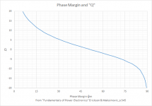
Maybe, maybe not. When you see an impedance peak re-run the analysis from 10kHz to 1MHz so that you can determine the "Q" of the impedance peak. There's not enough data to do it by eyeball.
Loop gain stability can be derived from Q by the Erickson/Maksimovich appromixation:
PM = 0.5363 * Q^(-0.907)
Sometimes you can get a false impedance bump by over-driving the output, overdriving the control loop.
And for the sake of consistency, the load should remain the same for all tests -- settle on 25mA -- as the load increases the impedance decreases because the transconductance of the pass device increases.
Attachments
Last edited:
use a zener instead of the cap, which does the same,
in the curryman cct, which has a cap and zener, if the zener is removed will there be any change in the noise output?
None if the output voltage is insufficient to make the zener conduct (which looks like the design goal), and an increase in DC to subsonic frequencies if it did. No big deal IMHO
Hmmm, I think on the 5V version the zener would have lower noise at low frequency... This would need a measurement, it would probably depend on what specific zener is used though.
But it will save the load from overvoltage if the pot fails open, or becomes scratchy as they eventually all do, which is a very nice feature...
But it will save the load from overvoltage if the pot fails open, or becomes scratchy as they eventually all do, which is a very nice feature...
Maybe, maybe not. When you see an impedance peak re-run the analysis from 10kHz to 1MHz so that you can determine the "Q" of the impedance peak. There's not enough data to do it by eyeball.
Yeah I might have cut some corners 😀
I admit remembering the "specifications" for the device did not inspire me much, not a word about what capacitors it likes, etc. Especially the use of LT1028 which is not specified as unity gain stable, in a circuit with a 100pF feedback cap from output to negative input, that makes it unity gain at HF.
And for the sake of consistency, the load should remain the same for all tests -- settle on 25mA -- as the load increases the impedance decreases because the transconductance of the pass device increases.
It can be made load invariant with a CFP pass device and a low value emitter resistor.
- Home
- Amplifiers
- Power Supplies
- Some power supply tests from the archives!