I built a DC power supply for about 12V (not critical) loaded by a constant 2.5A. The reservoir capacitor is 100000uF, but still there is too much ripple. I came to the idea to insert a choke between the diode bridge and the capacitor, forming an LC filter. I found a small laminated core choke with DC resistance 1.5 ohms. Since the DC voltage on the capacitor is 14.5V, I calculated the voltage would be 10.75V with the choke inserted.
However, I measured 7V DC on the capacitor. How it could be?
I know the choke should have an air gap for not going into saturation, but how does it affect its DC resistance? Why does it drop more voltage than I expected?
However, I measured 7V DC on the capacitor. How it could be?
I know the choke should have an air gap for not going into saturation, but how does it affect its DC resistance? Why does it drop more voltage than I expected?
The LC filter gives you the average rectified voltage, not the peak rectified voltage.
Instead split the capacitors into two equal groups and connect a 0.47 ohm 10W resistor
in series between them. Don't skimp on the power rating, it has to dissipate the ripple voltage too.
The resistor will drop about 1.3V, but will take the ripple down by a factor of around x15.
Instead split the capacitors into two equal groups and connect a 0.47 ohm 10W resistor
in series between them. Don't skimp on the power rating, it has to dissipate the ripple voltage too.
The resistor will drop about 1.3V, but will take the ripple down by a factor of around x15.
Last edited:
Icsazar there are 2 types of power suply filters. First a capacitive input filter the first type you formed was a capacitive input filter. With these the output voltage is about 1.41 X the AC input - about 2 V . Next we have what is called a choke input filter disregarding the dc resistance the output from a choke input filter if the inductor is large enough is about .9 X the AC input voltage. So it looks like your LC filter was acting like a choke input filter. There is a formulae to calculate the minimum inductance refered to as the critical inductance and this is related to the curent and voltage used and if the value in mh of the inductor is too low it won't act as a choke input filter.
")
Yes, I measured the peak-to-peak with an oscilloscope. The raw DC on the first 105000uF capacitor was 14.5V, ripple is 140mV sawtooth-like. Then I inserted a laminated core choke with air gap, salvaged from a PC SMPS. I did not measure the inductance, only the resistance about 1.5 ohms. It was pretty hot during the test (calculated dissipation is 9 Watts), so I will modify it using thicker wire, aiming lower resistance. The second capacitor is 33000uF, DC voltage on it is 10.75V and ripple is 5mV 100Hz quasi sine waveform.
Measurements with a single reservoir capacitor 105000uF:
Transformer secondary: 12.7VAC
Voltage on the capacitor: 14.45VDC
Load current: 2.4A
Ripple: 140mVpp
PSUD2 gives somewhat different results (see attached). I just estimated the secondary resistance and the ESR. In the real circuit there is a snubber on the transformer secondary.
Transformer secondary: 12.7VAC
Voltage on the capacitor: 14.45VDC
Load current: 2.4A
Ripple: 140mVpp
PSUD2 gives somewhat different results (see attached). I just estimated the secondary resistance and the ESR. In the real circuit there is a snubber on the transformer secondary.
Attachments
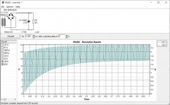
Icsaszar, PSUD2 shows circa 2Vpp ripple for 2.4A load, whereas you measure 140mVpp. Perhaps if you can review your measurement setup? Are you using a 10:1 scope probe?
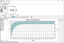
In PSUD2, if you make the reporting delay "1" sec then you can lower the simulation window duration to say 50ms and that allows a better view of the ripple waveform. If you expand the 'Result' sub-window then you can see relevant displayed waveform data.
In PSUD2, if you make the reporting delay "1" sec then you can lower the simulation window duration to say 50ms and that allows a better view of the ripple waveform. If you expand the 'Result' sub-window then you can see relevant displayed waveform data.
What kind of laminated inductor did you used? Is it the one for PFC on the PC PSU? I don't think they are gaped because made for 60hz AC and no DC current.
Can you post a picture?
It is the DC resistance of 1.5ohm that reduced the voltage and the ripple. In fact you crated a RC filter
The inductance should be really low as the core is saturated by DC current
Can you post a picture?
It is the DC resistance of 1.5ohm that reduced the voltage and the ripple. In fact you crated a RC filter
The inductance should be really low as the core is saturated by DC current
Last edited:
Hello,
If the choke is small then it will be one that you surely cannot use for a choke input with more than 2A running.
If you wanna use a TRUE choke input for your supply you will need a minimum number of mH ( the critical inductance) and you will need a choke with an airgap that can handle the big current. If not it will just work as an RC filter that will probably have some '' issues'' because it is used in the wrong location.
Greetings, Eduard
It is not a matter of resistance but inductance and impedance. Well, we can expect massive switching transients at 2.5 A. The choke input filter offers an effective treatment for the problem, but it also comes with some noteworthy practical drawbacks. You will probably have to give up on it.
Hello, a method that could work (simulation and test to do) to achieve under mV of ripple without big capacitors (it has a cost):
- Using a LMZ14203H or equivalent (switch reglator from TI or Analog devices) to have a more clean DC voltage after the output transformer (not only capacitor or LC filter). You can reduce the capcitors total value with regulator than without regulator.
- Then using a LDO to reduce the ripple in the 100µV range (PSSR of most of LDO are about 40-50dB at least in the 10-1MHz range). The LDO acts as an active filter.
What if the final voltage you need ? only 12V @ 2.5A or +/-12V @ 2.5A ? What is teh input voltage (AC or DC. I presume AC because you have a transformer).
Last edited:
Thanks for the idea, but I am satisfied with the current result. This is a tube preamplifier and I want to exclude any switch regulator.Hello, a method that could work (simulation and test to do) to achieve under mV of ripple without big capacitors (it has a cost):
- Using a LMZ14203H or equivalent (switch reglator from TI or Analog devices) to have a more clean DC voltage after the output transformer (not only capacitor or LC filter).
Now I think this thread can be closed.
- Status
- This old topic is closed. If you want to reopen this topic, contact a moderator using the "Report Post" button.
- Home
- Amplifiers
- Power Supplies
- LC filter after diode bridge