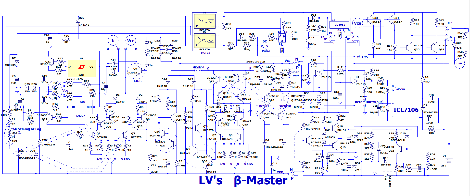
I had the frustration that the TL431 does not exist in a negative version. As a plain shunt regulator, the TL431 can be used both for positive and negative voltages. But combined with a pass-transistor and feed-back from the emitter output of that pass-transistor, the negative version is not evident.
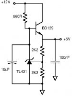
Pict. 1 shows the positive version known from among other the datasheet.
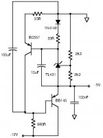
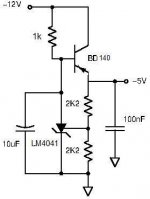
Pict.2 shows my suggestion for a negative version, implemented for an output voltage of -5V.
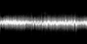
Pict. 3 shows the output noise of the negative version with a load current of 50mA. The scale is 1mV per main-division and 200uV per sub-division.
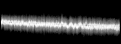
Pict. 4 shows the output noise of the negative version with a load current of 328mA. The scale is 1mV per main-division and 200uV per sub-division.
The “blur” on the scope pictures was also there without power on the voltage regulator. With a maximum sensitivity of my Hameg oscilloscope of 1mV per main division, the scope noise is visible and the main beam should be focused on.
The TL431 I used was an item marked “WS”, thus of a Chinese manufacture. It is a very cheap type I use for less critical purposes.
It can be seen that the -5V output has a noise level of less than 100uVrms with a loading of 50mA and close to 100uVrms at 328mA loading. Less than the LM317. This, with a TL431 of a very cheap type. The 100uF capacitor has to be adapted in size to the balance between noise and response speed.
Knowing that some members will consider this another example of someone who is not aware of the state of voltage regulators today, I still see some advantages of such a circuit. Having a few TL431 in your drawer, even of a very cheap type and a few ordinary transistors, quite well performing negative voltage regulators can be made according to your needs. With a trivial BD13X transistor, currents up to 0.5 A can be regulated. With a TO-220 or TO-247 Darlington transistor, currents up to 8A can be handled.
Pict. 1 shows the positive version known from among other the datasheet.
Pict.2 shows my suggestion for a negative version, implemented for an output voltage of -5V.
Pict. 3 shows the output noise of the negative version with a load current of 50mA. The scale is 1mV per main-division and 200uV per sub-division.
Pict. 4 shows the output noise of the negative version with a load current of 328mA. The scale is 1mV per main-division and 200uV per sub-division.
The “blur” on the scope pictures was also there without power on the voltage regulator. With a maximum sensitivity of my Hameg oscilloscope of 1mV per main division, the scope noise is visible and the main beam should be focused on.
The TL431 I used was an item marked “WS”, thus of a Chinese manufacture. It is a very cheap type I use for less critical purposes.
It can be seen that the -5V output has a noise level of less than 100uVrms with a loading of 50mA and close to 100uVrms at 328mA loading. Less than the LM317. This, with a TL431 of a very cheap type. The 100uF capacitor has to be adapted in size to the balance between noise and response speed.
Knowing that some members will consider this another example of someone who is not aware of the state of voltage regulators today, I still see some advantages of such a circuit. Having a few TL431 in your drawer, even of a very cheap type and a few ordinary transistors, quite well performing negative voltage regulators can be made according to your needs. With a trivial BD13X transistor, currents up to 0.5 A can be regulated. With a TO-220 or TO-247 Darlington transistor, currents up to 8A can be handled.
Attachments
Last edited:
Indeed, there is no way to make a complementary of the Fig 1 schematic.
That is very frustrating.
So.....
I simply only use the positive topology.
For +V 0 - V, I use transformers with dual secondaries feeding two diode bridges.
From these two independent positive regulated supplies, there is no problem to connect them to obtain common ground, positive and negative supplies.
This is indeed a possibility. But, not if you already have a 3-wire secondary (with mid-point). For noise sensitive applications I have a preference for a symmetrical +/- regulator circuit (with a regulator element in both the positive and negative rail) because two stacked positive regulator circuits leave the negative rail with direct connection to the rectifier bridge, which may leave noise on the negative rail.
Of course, you do need two independent secondary windings.This is indeed a possibility. But, not if you already have a 3-wire secondary (with mid-point).
I do not see why. What sort of noise ?For noise sensitive applications I have a preference for a symmetrical +/- regulator circuit (with a regulator element in both the positive and negative rail) because two stacked positive regulator circuits leave the negative rail with direct connection to the rectifier bridge, which may leave noise on the negative rail.
Has this been observed and measured ?
In my latest "Betamaster" version, I happened to use such a regulator.
I initially intended to use a more standard solution, like a LM338 or LM396, but the transformer was not capable of supplying enough voltage with a 5A DC load to allow the regulation of the 25V output (a dropout <1V was required).
This meant that I had to design an ultra-LDO from scrap.
I used a very low Rdson MOS, and I opted for a negative version because PMOS are rarer and weaker than their N counterparts (it is a floating, single supply).
The circuit is visible at the bottom right of this schematic:
I didn't particularly refine it: it is just a workhorse, and it just needs to be stable and regulate accurately, which it does.
Nothing is done to mitigate the noise of the reference, or push the dynamic performances.
This could be done with the addition of judiciously located capacitors
Well ... there is the LM4041 🙂I had the frustration that the TL431 does not exist in a negative version.
Mona
.......................................
I do not see why. What sort of noise ?
Has this been observed and measured ?
My worry is noise arising from capacitive coupling between the two secondary windings that is then found on all four output wires. As a principle, I like to have only one reference line (ground) with possible noise from the transformer and two lines I can regulate relative to that reference line.
Observed? Not a frequent problem as most get away with the stacked design. Measured? Admittedly not by me as I use the symmetrical design.
Perhaps I exaggerate the problem but at least I can use the TL431 also for regulation of negative voltages. The few extra components required I do not see as a disqualification.
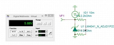
Well ... there is the LM4041 🙂
Mona
I did not know the LM4041. A quick look at the datasheet leaves me with the impression that it is a micro-power -type TL431. But, is the problem of regulating negative voltages different from using the TL431?
I find TL431 attractive because it is inexpensive or really cheap depending on the manufacture, it can handle quite some current (if cooled well), has respectable performance and can be used for regulating positive and negative voltages up to many amperes depending on my sudden needs. A kind of a "Swiss knife" for varying DIY applications.
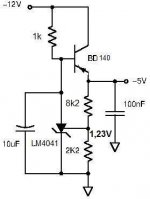
The negative regulator using TL431 as shown in Fig2 is the topology I used in September 2020 in posts #1102, #1111 of D-Noizator: a magic active noise canceller to retrofit & upgrade any 317-based V.Reg. - Page 111 - diyAudio
The trick is to use a current mirror to create a complimentary version of TL431. In Fig2 the current mirror is made of the two 33 ohm resistors, the diode 1N4148 and the bjt BC557.
The trick is to use a current mirror to create a complimentary version of TL431. In Fig2 the current mirror is made of the two 33 ohm resistors, the diode 1N4148 and the bjt BC557.
Last edited:
The reference voltage appears between the positive terminal and the adj pin, it is thus more or less the reverse of a TL431 (not quite, but a negative substitute with characteristics that can be made equivalent if the performances are sufficient).I did not know the LM4041. A quick look at the datasheet leaves me with the impression that it is a micro-power -type TL431. But, is the problem of regulating negative voltages different from using the TL431?
The current and voltage ratings are another story
Sorry, you were first  . I did not follow that thread as I had bought some (cheap) regulator boards using LF356 for noise cancelling.
The components you describe indeed form a rough current-mirror.
I found another negative voltage implementation back from 2006 but it was made such that the base-emitter voltage of the pass-transistor formed part of the TL431 reference voltage. For coarse regulation that will do but the stability is importantly degraded. This is why I like the current-mirror solution better.
. I did not follow that thread as I had bought some (cheap) regulator boards using LF356 for noise cancelling.The components you describe indeed form a rough current-mirror.
I found another negative voltage implementation back from 2006 but it was made such that the base-emitter voltage of the pass-transistor formed part of the TL431 reference voltage. For coarse regulation that will do but the stability is importantly degraded. This is why I like the current-mirror solution better.
The reference voltage appears between the positive terminal and the adj pin, it is thus more or less the reverse of a TL431 (not quite, but a negative substitute with characteristics that can be made equivalent if the performances are sufficient).
The current and voltage ratings are another story
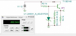
OK, the reference voltage is between cathode and reference and not as for TL431 between reference and anode. Then I understand how it can be used directly for regulation of negative voltages. I missed that detail in the datasheet.
Merci!
That is another story when the -12V is not a fixed voltage but an unregulated PSU voltage. Then the current thru the "zener" varies a lot under load and line variations. So, it is likely, you need a CCS, which incidentally brings other benefits. I use a ring of two bjt. This looks more complex ( 2 transistors and 2 resistors instead of 1 resistor ) but that is compact, no brainer, and any cheapos will do.

LM4041 is indeed what I was looking for concerning a negative version of the TL431. I checked the price at Mouser and it is more expensive than the TL431, but not dramatically much, and can be supplied in the TO-92 housing. The only limitation is the considerably lower current handling. For most low power circuits it will do including head-phone amplifiers but for several amperes it is a bit just, even with a Darlington pass-transistor. Thank you for making me aware of the LM4041.
- Home
- Amplifiers
- Power Supplies
- TL431 and pass-transistor for negative voltages.