Hi folks
I've built a pair of this simple JFET pre-amp, substituting a BF256B for the BF245B and a 2SA1175 for the BC560.
I'm wondering how to power them, what sort of regulator to use, there are so many options from the humble 78xx IC to really complex fully discrete circuits.
I'm not sure how exotic a regulator this circuit needs to sound good, I like the idea of a discrete circuit rather than an IC, but would that be overkill for this pre-amp?
Is there a discrete circuit that offers better performance than a 78xx or LM317 that is pretty simple with a fairly low parts count?
I'm open to suggestions and in need of guidance.
Attachments
Check out this thread:
Just for fun: a superreg with <12 discretes??! ?! ?
Just for fun: a superreg with <12 discretes??! ?! ?
Cheers.
I note that the simple discrete regulator EUVL posted in that thread is stated to not offer any greater performance than a 78xx regulator IC:
Voltage Regulator From Discrete Components

I suppose what I'm asking, is that is it possible to better the performance of an LM317 with a 10uF tantalum cap added with a simple discrete circuit?
Elvee's design looks interesting and pretty simple, but I'm not able to follow and understand all he wrote in the thread aboutit, is it a working circuit or just the start point of a work in progress? He mentions it is not self-starting, I don;t know what he means there.
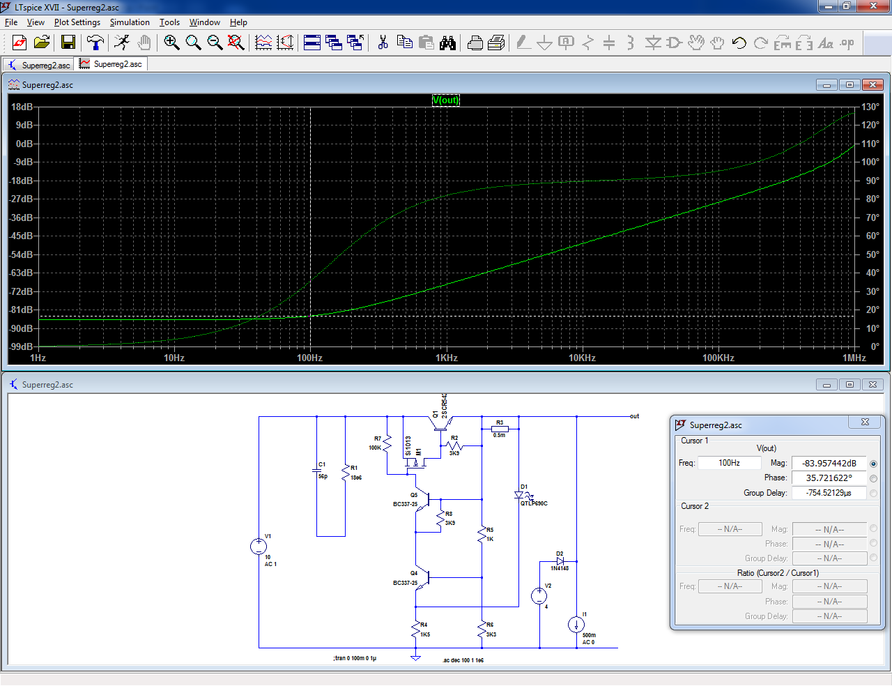
I note that the simple discrete regulator EUVL posted in that thread is stated to not offer any greater performance than a 78xx regulator IC:
Voltage Regulator From Discrete Components
I suppose what I'm asking, is that is it possible to better the performance of an LM317 with a 10uF tantalum cap added with a simple discrete circuit?
Elvee's design looks interesting and pretty simple, but I'm not able to follow and understand all he wrote in the thread aboutit, is it a working circuit or just the start point of a work in progress? He mentions it is not self-starting, I don;t know what he means there.
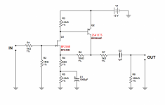
I found this page with a very simple Zener-Emitter Follower based regulator that has a lot less noise than an LM317 ciruit, so I think I'll build theis and try it out:
Simple Voltage Regulators Part 1: Noise
Although not clearly stated, it looks to me like the input voltage is 21V, the preamp I want to power needs at least 12v and due to the capacitors I used, will take a max of 16v. I'm wondering, do I need to make some changes to the values of the resistors in this regulator circuit to get an output between 12 and 16v? I was planning to use a small toroidal trafo that has two secondaries of 18v at 194mA, 18v AC rectified I think gives about 21v DC, so between the rectifier and the preamp I need to drop at least 5v I think. I was thinking of adding a ripple eater filter after the regulator as I already have a pair of ripple eater circuits I built a while back I can use, I don't know what the combined voltage drop will be of the regulator and ripple eater, will I need to measure the voltage before it goes into the preamp and if necessary, add a resistor to drop it below 16v?
I don't have BC560B and BC547C transistors, I do have BC327 and BC337. Looking at the OnSemi datasheets, they look to be direct equivalents but OnSemi calls the 560 and 547 'low-noise' whereas it doesn't use that label for the 327 and 337.
I also have SS8050 and SS8550 transistors I could use, but I have no idea how these various options compare in terms of noise, they all seem close enough in electrical characteristics to work in this circuit.
Any thoughts or info on transistor selection before I go ahead and build this circuit?
Simple Voltage Regulators Part 1: Noise
"[FONT=Arial, Helvetica]This is a variation of a simple shunt regulator design that has been floating around on the net. It is a unity-gain (thanks to the feedback through C1) amplifier that consists of gain-element Q1 and follower Q2. In this particular instance the open-loop gain of Q1 is enhanced beyond the ordinary by the large-valued resistor R3, coupled to the intermediate 15V supply voltage found between droppers R2 and R10. This excess gain serves in reducing the closed loop output impedance of this regulator to a low 50 mOhms, right out to 1MHz. Alternative schemes are possible that give even more open-loop gain, namely using an active load for Q1. Running at these gains may necessitate some form of compensation to keep the circuit stable: indeed one of my four implementations breaks into mild (*) oscillation once in a while, unless 22pF is present between Q1's collector and ground."[/FONT]
Although not clearly stated, it looks to me like the input voltage is 21V, the preamp I want to power needs at least 12v and due to the capacitors I used, will take a max of 16v. I'm wondering, do I need to make some changes to the values of the resistors in this regulator circuit to get an output between 12 and 16v? I was planning to use a small toroidal trafo that has two secondaries of 18v at 194mA, 18v AC rectified I think gives about 21v DC, so between the rectifier and the preamp I need to drop at least 5v I think. I was thinking of adding a ripple eater filter after the regulator as I already have a pair of ripple eater circuits I built a while back I can use, I don't know what the combined voltage drop will be of the regulator and ripple eater, will I need to measure the voltage before it goes into the preamp and if necessary, add a resistor to drop it below 16v?
I don't have BC560B and BC547C transistors, I do have BC327 and BC337. Looking at the OnSemi datasheets, they look to be direct equivalents but OnSemi calls the 560 and 547 'low-noise' whereas it doesn't use that label for the 327 and 337.
I also have SS8050 and SS8550 transistors I could use, but I have no idea how these various options compare in terms of noise, they all seem close enough in electrical characteristics to work in this circuit.
Any thoughts or info on transistor selection before I go ahead and build this circuit?
Last edited:
How much current you need? My 5 op amp 36 ma disco mixer uses zener diodes preceded by a 22 ohm resistor on each side. Peavey uses 1.3 W zeners in nearly all their power amps, regulating down from 60-80 v. Make sure load current is > 5% of zener watt rating.
The cs800s has zener regulation for about 3 op amps per channel and is specified at .03% HD at 400 w/ch.
I use e-caps before & after. some hum leaked through my disco mixer so I used a double pi after zener, with 2 ohms between each e-cap stage. Improving a "Disco mixer" to mid-fi performance - diyAudio
My disco mixer after op amp & power supply upgrade now sounds better than my PAS2 tube preamp. PAS2 had some paper GI caps degrade in 50 years; mylar replacements hurt the sound some.
Please use an RC filter at the input (and a volume controller, RC filter before the volume control). Use a large value cap for C7 like 4.7 µf. Add a muting relay to prevent inevitable power on/off plops.
For 12V a LT3042 regulator will give best results when power consumption is below 200 mA. Should be way lower than you expect. Improving on a LT3042 is a hard task. Since the PSRR of the circuit won't be optimal the best PSU will give best results here. That comes with this specific circuit.
BTW how much gain do you need?
Last edited:
....I'm not sure exactly how much current it will consume, but I expect somewhere between 100 and 150mA.....

Even if both transistors are dead-short, it's all like 10k and 2.2k resistors. 100mA in 10k is a thousand volts. You only got twelve.
For quick estimation, assume the final device and its resistor split the supply "50:50". It may be 33:66 or 66:33 but no great difference.
Rapid estimation IS a useful skill in DIY. It saves you from coming back from the lumberyard with two tons of wood for a small doghouse.
Attachments
Rapid estimation IS a useful skill in DIY. It saves you from coming back from the lumberyard with two tons of wood for a small doghouse.
I salute you sir for this beautiful analogy.
Last edited:
This is all excellent information, thankyou.
Now you see my purpose in building this thing - I am only a beginner and really don't know what I'm doing, despite all the study I've done thus far, so I thought it was a good idea to build some simple circuits using a small number of cheap components like common small signal transistors and 1/4w resistors as a learning exercise - if it blows up, sets on fire or melts, I haven't lost much in monetary value but have gained much in knowledge and experience.
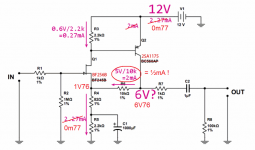
So, that simple preamp circuit has a consumption of 2.27mA, I'm not sure I understand how exactly you calculated that, I need to learn more in that area, clearly.
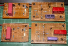
Here's the circuits I have built so far, the two pre amp modules on the right, the two on the left are ripple eaters I built a while back and never used, I used BC327 & BC337 trannies instead of the 2N5087 & 2N5089.
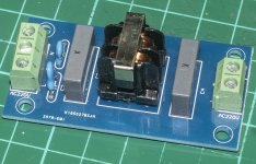
The other pic is the RC filter I have. I hadn't thought about a speaker protection circuit, wouldn't that be placed in the power amp?
How much gain do I need? I don't know, I haven't got as far as deciding what power amp I'm going to use with this, I was thinking as simple design as possible, so I'm open to suggestions, perhaps a class AB push-pull type or a class A type with a jfet driving a power mosfet, I'd like, as far as possible to use the components I already have as I have accumulated a large stash of them. I've looked at so many amp topologies and circuits I've confused myself, so suggestions as to what would be a suitable simple, easy design to build for a beginner is much appreciated.
Now you see my purpose in building this thing - I am only a beginner and really don't know what I'm doing, despite all the study I've done thus far, so I thought it was a good idea to build some simple circuits using a small number of cheap components like common small signal transistors and 1/4w resistors as a learning exercise - if it blows up, sets on fire or melts, I haven't lost much in monetary value but have gained much in knowledge and experience.
So, that simple preamp circuit has a consumption of 2.27mA, I'm not sure I understand how exactly you calculated that, I need to learn more in that area, clearly.
Here's the circuits I have built so far, the two pre amp modules on the right, the two on the left are ripple eaters I built a while back and never used, I used BC327 & BC337 trannies instead of the 2N5087 & 2N5089.
The other pic is the RC filter I have. I hadn't thought about a speaker protection circuit, wouldn't that be placed in the power amp?
How much gain do I need? I don't know, I haven't got as far as deciding what power amp I'm going to use with this, I was thinking as simple design as possible, so I'm open to suggestions, perhaps a class AB push-pull type or a class A type with a jfet driving a power mosfet, I'd like, as far as possible to use the components I already have as I have accumulated a large stash of them. I've looked at so many amp topologies and circuits I've confused myself, so suggestions as to what would be a suitable simple, easy design to build for a beginner is much appreciated.
Attachments

If you don't know the gain of the power amplifier then it is a question mark if you need a preamp at all. Most power amplifiers have enough gain for modern 2V rms/10 kOhm sources. You would then only need source selection and volume control. So in reality you either need no preamp or if you persist you could build a low gain preamp or buffer which has no gain.
Your preamp will have nasty power on/off behavior without muting and a power amplifier is "open" thus it will amplify that power on/off phenomenon multiplied with its gain. There is a chance your speakers will not like that.
The RC filter you show is a mains filter. RC exists of R and C or a low pass filter to prevent non audio signals coming in.
While it can be a nice pastime to do something, it would be more efficient to plan stuff and what it is you exactly need. Don't think a discrete design is always better than an IC design, there are many excellent performing IC's. Design can be simpler as well. Try to avoid building "one offs" that only work together. Keep to standards when possible.
If you want a more or less guaranteed success then this is a very well performing and simple discrete buffer with all bells and whistles:
Mezmerize B1 Buffer – diyAudio Store
Last edited:
I am afraid your doghouse will be out of proportion, 5/10 = 2
Even if both transistors are dead-short, it's all like 10k and 2.2k resistors. 100mA in 10k is a thousand volts. You only got twelve.
For quick estimation, assume the final device and its resistor split the supply "50:50". It may be 33:66 or 66:33 but no great difference.
Rapid estimation IS a useful skill in DIY. It saves you from coming back from the lumberyard with two tons of wood for a small doghouse.
And the values don't go well with the BF256B data. Not enough -Vgs and up goes the current saturating Q2. With a BF256A it is more like it.But with the spread of the properties of fets, best make R3 adjustable.
And who needs the over 100x gain
Mona
Attachments
And who needs the over 100x gain
Mona
No normal person needs that for sources but the habit of adding tons of useless gain is common under audio DIYers.
Or is it a preamp for microphones?
I found the circuit here:
Simple JFET Preamp - AUDIO WORKSHOP
It might be simple and elegant but if it's got too much gain and loads of distortion, it's hardly what I need.
Should I just discard this preamp design and start over?
Simple JFET Preamp - AUDIO WORKSHOP
"A JFET preamp for beginners. Simple yet elegant. Low noise.
The following is an example for a very simple and high quality JFET preamp."
It might be simple and elegant but if it's got too much gain and loads of distortion, it's hardly what I need.
Should I just discard this preamp design and start over?
Yes, like the article says is this device for low signal level sources which are not around anymore since 40 years (unless one has a classic phono setup).
So: determine what sources you have and what signal levels (my guess: 2V rms) and how many, then decide on how many inputs the amplifier must have. If you choose a power amplifier with enough gain and high input impedance you don't need anything in front of it except source selection and volume control.
So: determine what sources you have and what signal levels (my guess: 2V rms) and how many, then decide on how many inputs the amplifier must have. If you choose a power amplifier with enough gain and high input impedance you don't need anything in front of it except source selection and volume control.
Last edited:
- Status
- This old topic is closed. If you want to reopen this topic, contact a moderator using the "Report Post" button.
- Home
- Amplifiers
- Power Supplies
- Regulator for Pre-amp