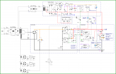
I am planning to develop an adjustable power supply from 1 to 30v / 7A, with the LM723.
I decided to try the TL7660 voltage converter to obtain a negative voltage. Powered by the LM723 Vref.
With Pin 7 of the LM723 set at -2.7v, the minimum output voltage (1v) is presented with good stability.
I chose to control the output voltage, changing the voltage of the non-inverting input (pin 5), keeping the gain fixed at 13 (pin 4).
In my experiments, when I pull a load of 30ma at the output, there is a small change in Vref (pin 6). The problem is that this small change in Vref is also affecting LM336. The value in LM336 rises approximately 1mv, resulting in an increase of 13 mv in the output. I tested with several LM336 but the result is the same. Any suggestions for improving the stability of the LM336?
Are you trying to build a lab power supply? You do realize you need an external transistor for high currents from the LM723?
If so, nearly all lab power supplies have a different way of doing things.
Edit, its late and im sleepy but lab power supplies is my thing. so im gonna try to give you some advice. Plus i see that you are good, your circuits look good and well thought out.
Most lab power supplies take the reference, and put in on top of the positive output, the reason behind it, is that you can compare with an opamp the error between a resistor divider from reference to the minus of the supply. This also means that the opamp will see the FULL ERROR SIGNAL. so it will have much better regulation. Examples of this are the DIY project in the Dutch Elektuur from 1982, this supply is still very good..
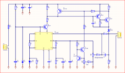
Attached you will find the schematic of a ultra low noise lab power supply by a Dutch electronics forum member. This supply beats most of the stuff on the market..
You can simplify this schematic, and use the 723 as the +10V regulator.
If so, nearly all lab power supplies have a different way of doing things.
Edit, its late and im sleepy but lab power supplies is my thing. so im gonna try to give you some advice. Plus i see that you are good, your circuits look good and well thought out.
Most lab power supplies take the reference, and put in on top of the positive output, the reason behind it, is that you can compare with an opamp the error between a resistor divider from reference to the minus of the supply. This also means that the opamp will see the FULL ERROR SIGNAL. so it will have much better regulation. Examples of this are the DIY project in the Dutch Elektuur from 1982, this supply is still very good..
Attached you will find the schematic of a ultra low noise lab power supply by a Dutch electronics forum member. This supply beats most of the stuff on the market..
You can simplify this schematic, and use the 723 as the +10V regulator.
Attachments
Last edited:
To achieve the desired stability in the LM336, I observed that the current must be as constant as possible. By adding a simple current source, the desired objective was achieved. From the 13mv increase at the exit it dropped to just 3mv.
In practice, a maximum current of 7ma from 723 will be required when the Darlington transistor is implemented. At 7ma, Vref is very stable, not affecting the LM336. Despite the stability, I will keep the current source for the LM336. I think it would be even better using the LM334 for the current source.

In practice, a maximum current of 7ma from 723 will be required when the Darlington transistor is implemented. At 7ma, Vref is very stable, not affecting the LM336. Despite the stability, I will keep the current source for the LM336. I think it would be even better using the LM334 for the current source.
As I see it, you are loading Vref of the LM723 far too much. Vref stabilized is nominally 7.15V. You measure 4.4V! In the datasheet, I did not spot the maximum current from Vref with this voltage regulated. Absolute Maximum Ratings according to the datasheet are 15mA but that is avoid destruction, not ensure regulation.
Buffer Vref with a BD135/137/139 transistor: collector to Vdd (35V), emitter to pin 8 of the TL7660 (and the LM336 bias circuit) and base to pin 6 of the LM723 (Vref). Your emitter voltage should then be around 6.5V.
Buffer Vref with a BD135/137/139 transistor: collector to Vdd (35V), emitter to pin 8 of the TL7660 (and the LM336 bias circuit) and base to pin 6 of the LM723 (Vref). Your emitter voltage should then be around 6.5V.
FauxFrench, thank you very much for your feedback!
Vref of LM723 and referenced by pin7. Pin 7 was removed from GND for the negative value of -2.7v. Vref has a value of 7.10 - 2.7 = 4.4v in relation to GND. From pin 6 (Vref) to Pin 7 the voltage continues at 7.10v.
The nominal current that passes through Pin 7 of the LM723 is 1.9ma. The total current measured through Vref (pin 6) is 6.04ma. Therefore, working perfectly within the safety parameters.
A LM358 voltage follower is going to load the reference less, and has no VBE temperature drift. From what i remember the VBE voltage in a transistor varies -2mV per Kelvin
Also pin5 is an opamp input. you can use a simple voltage divider from the reference. Because right now you are using the reference output for clean voltage and feeding that into a constant current source that feeds into a reference that is more accurate but not more stable.
The internal reference of the 723 is excelent.
Last edited:
Oh, i would caution you against a darlington like the TIP there is already a driver transistor inside the 723. if you add two more you get quite a slow output.
Something like the 2SC5200 would be ideal, as it has high gain, you can drive it directly with 723.
My previous remark about the reference: Some references are very accurate but not stable, some are very stable but not accurate, an example of this is the 1n821 temperature compensated zener virtually no temperature drift. But they can be 6.8-7.4V so you need to trim the output to get exactly the voltage you want.
v4lve lover, thank you very much for your precious help!
I will follow your advice and test the 2sc5200.
I did a clean and bet on the quality of the LEDs. The stability of the output voltages was fantastic! Tests with low output values 1v, 2v, 3v, .. perfect! I used loads pulling 5, 10 and 20ma.

I will follow your advice and test the 2sc5200.
I did a clean and bet on the quality of the LEDs. The stability of the output voltages was fantastic! Tests with low output values 1v, 2v, 3v, .. perfect! I used loads pulling 5, 10 and 20ma.
I made a mistake in the design above, reversing the polarization of the LEDs.
I had to raise the voltage to the control pot, adding two orange LEDs. With that I was able to reduce the gain to 8.53 and thus decrease the sensitivity of the pot.
I tested the potentiometer directly on the Vref, to further reduce the gain, but it resulted in small variations in the output voltage, in the load variations. I went back to using the LEDs and it was spectacular! I confess that I was surprised at how good the output voltage regulation was for all ranges.
hello avelino,
just a suggestion: if you allow the output to be 2 - 30 volts you can omit the negative supply workaround with all it's disadvantages and have a stable and precise reference voltage by the LM723 rather than relying on LEDs.
on the other hand: if you include a negative supply why not go all the way from 0-30 volts?
regards
v4lve lover, thank you very much for your precious help!
I will follow your advice and test the 2sc5200.
I did a clean and bet on the quality of the LEDs. The stability of the output voltages was fantastic! Tests with low output values 1v, 2v, 3v, .. perfect! I used loads pulling 5, 10 and 20ma.
Dont get them on ebay.. Those are fake. Same for Aliexpress
Sandy, thank you very much for presenting an alternative project.
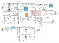
I made one more adjustment and this should be my final configuration. Note that now I have combined the blue led with the orange led, raising the voltage. With this new configuration I was able to reduce the gain to 6.8 and improve the sensitivity of the 10k potentiometer (10 turn). I replaced the blue led with the orange led, reducing the voltage on pin 7 from -2.7v to -1.77v.

I made one more adjustment and this should be my final configuration. Note that now I have combined the blue led with the orange led, raising the voltage. With this new configuration I was able to reduce the gain to 6.8 and improve the sensitivity of the 10k potentiometer (10 turn). I replaced the blue led with the orange led, reducing the voltage on pin 7 from -2.7v to -1.77v.
Hi Avelino,
I have some comments on your uA723 schematic.
Your DC stability depends on the Ri of the Blue LED.
By that I mean if the load varies from your power supply.
Because of the relatively high Ri of a Blue LED compared to e.g. LM3356 2.5V o a TL431.
Both ICs have a Ri far below 1 Ohm.
Of course your DC stability also depends on your two orange LED, but these are already fed from a reference voltage.
The variation that can still occur can be due to the impedance of the runner of your potmeter, which in the worst case is 1/4 of the value of the potmeter which in your case is 10/4 is 2K5.
The variation that can occur comes from the variation of the bias current due to the runner value of your potentiometer and the resistor in series with it.
The non-inverting input sees an impedance varying between 1K and 3K5.
That may not be a problem, but try doing tests when the potentiometer is in the middle position, do you see any difference in behavior?
Some more comments...
Your sense resistor R5 of 10K should be mounted on your output terminals for the lowest possible Ri of your power supply.
The - should be connected directly from your buffer electrolytic to the - terminal on the front of your power supply.
The "0" of your power supply board goes with a separate wire to the - terminal on the front.
Across your sense resistor R5 of 10K there is now 3nF as a capacitor.
Make this capacitor at least 0.1uF.
That will avoid a lot of 1/F noise.
I can't measure the noise behavior of this circuit for you, that would take way too much time and I don't have that available.
Yours sincerely,
Bram
Bram
Sorry for my delay in returning. I was waiting for a new purchase of the LM723. I was assuming the low quality of the 723 under test, as Vref was showing significant variation. I realized that it was related to the increase in temperature of the integrated circuit. I was trying to compensate for the variations with the Led's. With the new LM723, Vref was very stable, allowing to simplify the project.

Sorry for my delay in returning. I was waiting for a new purchase of the LM723. I was assuming the low quality of the 723 under test, as Vref was showing significant variation. I realized that it was related to the increase in temperature of the integrated circuit. I was trying to compensate for the variations with the Led's. With the new LM723, Vref was very stable, allowing to simplify the project.
Hi Avelino,
As said by SandyTodorov1 you do not need a negative supply to shift down the minimun voltage of a variable 723 based supply.
The following Blog article describe a very smart implementation :
Bench 0-30V 0-1A2 PSU (Part 1): Linear Regulator PCB | Hobbylad's blog
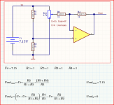
As opposite to the usual implementation this circuit is not based on a variation of the loop gain which combined to a fixed reference allow you to change the output voltage. Here loop gain is constant, reference is also fixed (on + input) but - input is a function of the output voltage and the expected output voltage value.
Simple and smart !
Chris
As said by SandyTodorov1 you do not need a negative supply to shift down the minimun voltage of a variable 723 based supply.
The following Blog article describe a very smart implementation :
Bench 0-30V 0-1A2 PSU (Part 1): Linear Regulator PCB | Hobbylad's blog
As opposite to the usual implementation this circuit is not based on a variation of the loop gain which combined to a fixed reference allow you to change the output voltage. Here loop gain is constant, reference is also fixed (on + input) but - input is a function of the output voltage and the expected output voltage value.
Simple and smart !
Chris
- Status
- This old topic is closed. If you want to reopen this topic, contact a moderator using the "Report Post" button.
- Home
- Amplifiers
- Power Supplies
- Adjustable power supply from 1 to 30v with the LM723 + TL7660 + LM336