Hey all. I just have what I am anticipating to be a couple quick questions. Some background to begin with: I have an old Peavey PA-900 mixer/power amp that I'm planning to remove power amp from, leaving the preamp section for recording purposes. Given that, I'm working on building a lighter-weight power supply. There is only one DC source to the entire preamp section so I can see that I'm working with around 50vdc and 50mA current draw. Best I can tell each channel has a couple transistors working as voltage regulators so I don't need to build a regulated supply. I have experience with tube amps, but when it comes to solid state circuits, things are done a bit differently and I feel a bit out of my element. Hopefully you guys can help.
Questions:
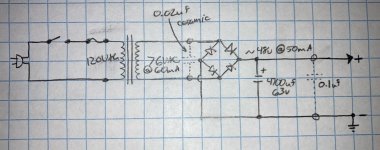
1. Is a simple supply like the one I've drawn up and attached below sufficient?
2. I've noticed on the current supply that there is 0.02uf ceramic cap across the transformer secondary leads, what does that do and is it necessary to replicate?
3. Similar question (function and necessity) for the 0.1uf cap in parallel with main filter cap to ground.
and...
4. Are there any basic safety features I should add?
Thanks in advance for any help!
Questions:
1. Is a simple supply like the one I've drawn up and attached below sufficient?
2. I've noticed on the current supply that there is 0.02uf ceramic cap across the transformer secondary leads, what does that do and is it necessary to replicate?
3. Similar question (function and necessity) for the 0.1uf cap in parallel with main filter cap to ground.
and...
4. Are there any basic safety features I should add?
Thanks in advance for any help!
Attachments
The details matter. Have you ever use a simulator like Spice? I use LTSpice.
You show diodes and caps, but not which ones. Diodes need to be at least twice PIV from the AC. 3X better. Be sure their average and surge current ratings are good.
The cap across the secondary is not correct. Search this forum for "snubber" circuits. Read about use of caps across the rectifiers or not.
You may search and read up on old school rectifier diodes vs fast recovery or Schottky. Then maybe read what Nelson Pass has to say on it.
The bypass on the filter cap will help with noise, not not ripple which will be the elephant in the room. It was a big DIY mod, but actually, not much use. Does not hurt, just may not help. Picking the best main cap is far more important. ( or use of multiple caps) The best place for sprinkling .1's around is right as the consumers of the power. Not back in the PSU.
A MOV on the transformer side of the fuse is good SOP.
The main filter cap is not just volts and uF, but needs to handle the ripple current.
An unregulated simple supply will likely not even get below 40dB on ripple and noise. You may want to consider a filter choke or CRC filter. If you can afford the voltage, those resistors really cut down on surge and will allow much larger caps. Even a pair of 2700u with one ohm between them will give a really significant reduction in ripple
I like to put the power indicator light on the DC side but some prefer it on the primary side.
Definitely do a CRC or CLC supply as tvrgeek suggested. The resistor in the CRC filter can also be used to fine tune the final output voltage.
You show a full wave bridge capacitor input supply. With diode losses the output voltage will be approximately 1.25 to 1.30 times transformer secondary VAC. Your 76VAC is way too high for 48VDC output. Also size the transformer for at least twice the current draw.
You show a full wave bridge capacitor input supply. With diode losses the output voltage will be approximately 1.25 to 1.30 times transformer secondary VAC. Your 76VAC is way too high for 48VDC output. Also size the transformer for at least twice the current draw.
Hey thank for the replies, guys. So firstly, guess I'll do away with that .02, then. Second, no I've never really used a simulator. I tried LTSpice, but I got impatient and decided to just draw it out. Not like it's that complicated of a circuit. Maybe I'll give it another go, though.
I'm OK going with a choke, I'll just size the transformer to whatever I need after voltage drops and the like. So if I go with a pair of 2700uf caps with a choke in between, that should be a decent start? As for ripple current, I was gonna shoot high and go for something around 2-3A. Is there a drawback to going too high?
Also sorry about not labeling the diodes, I was planning on some 1N5408 (probably overkill), but I'll read up on that and see what info there is about different kinds, for sure.
With regards to the power trans secondary voltage, I was using an online calculator which it looks might have been a little off. I'll go for something closer to 60 per your recommendation, Ben Mah.
And I've never even heard of an MOV (just looked it up). I'll read up on it for sure, though.
And finally, the mixer has a couple backlit VU meters on the front so I'm good on the power indicator department.
1) Where is the Peavey PA900 schematic?
Without it, answers won´t be much more than guesses.
2) why even *mention* filter inductors here?
3) 76VAC mean sizzling 107V DC which will murder the main filter cap, and the restof the mixer circuit.
IF you need 48VDC (where did you pull that value from?), you need 34V AC
4) with that large main capacitor and 50mA consumption, ripple is not an issue.
In any case we need the schematics to know what are we dealing with.
5)
6)
Please try to get the schematic and upload it here, it´s a somewhat obscure model.
Without it, answers won´t be much more than guesses.
2) why even *mention* filter inductors here?
3) 76VAC mean sizzling 107V DC which will murder the main filter cap, and the restof the mixer circuit.
IF you need 48VDC (where did you pull that value from?), you need 34V AC
4) with that large main capacitor and 50mA consumption, ripple is not an issue.
In any case we need the schematics to know what are we dealing with.
5)
Did you measure that?I can see that I'm working with around 50vdc and 50mA current draw.
6)
How do you know?Best I can tell each channel has a couple transistors working as voltage regulators so I don't need to build a regulated supply.
Please try to get the schematic and upload it here, it´s a somewhat obscure model.
Hey JM, Yeah I measured the voltage and current draw myself. That's how I got the 50v number (it actually reads 53v, but the filter cap at the preamp input is only rated for 50v). My 48v is mostly just an arbitrary "50-ish" target. I emailed Peavey for a schematic a couple days ago and am waiting on a response. Hopefully they can supply it so I have some more info and I can post it here.
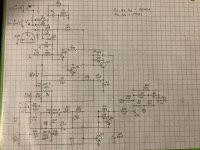
I have schematic of one individual preamp I drew up from tracing the PC board myself. Might have a couple inaccuracies, but it's very clear that the incoming power goes through a 100ohm resistor and directly to the collectors of two separate transistors, which I believe is an orientation indicative of voltage regulation. I'll post a pic below. I could be completely wrong (probably am).
Sounds like you're thinking I don't need the LC filter given the low current draw, then?
The current power is basically just a 10,000uf/60v cap coming off the full wave bridge rectifier diodes and straight to the preamp. Guess I was kind of using that as a template to replicate and improve upon a bit if possible. But yeah I'll definitely post the schematic if/when I can get it from Peavey.
And yeah, my bad on the VAC thing. Read Ben Mah's calculation backwards. Mid-30's VAC it is.
Attachments
- Status
- This old topic is closed. If you want to reopen this topic, contact a moderator using the "Report Post" button.
- Home
- Amplifiers
- Power Supplies
- Basic Power Supply Design