Been doing some small improvements to existing low power circuits. Preamp, crossover, DAC etc. Playing with SMPS to reduce ripple and using R-C-R-C filters. Both quite effective and the R-C filter does wonders for reducing current spikes through the rectifier, or if using an SMPS whose tolerance for driving a large C load is suspect in my mind. Getting a 10X reduction in ripple is pretty easy. Nothing to sneeze at. But not quite enough to push the ripple below the noise floor.
So, looking at a capacitance multiplier. Much lower transient current than a bigger cap. Less loss than the large-ish resistors in my RCRC and easily over 100x ripple reduction. 1000x if I give up a little more voltage.
So what is the down side? Cost? No as big caps cost a lot more than transistors even adding a heat sink. Space? Not really. Ability to handle transient loads? Not important if feeding a LDO regulator, but maybe not good for an unregulated power amp supply?
I'd say transient load, as a real cap can sink current as well as source it, whereas a fake multiplied cap can only source current. Unsure if it matters if current load is always sinking; such as with class A circuitry being powered.
I hazily recall someone years ago reporting sonic improvement using "shunt" regulation, which perhaps provides a current sinking path, as well as sourcing it. I've always thought why not just use a unity gain stable power op-amp set to a voltage? Nothing's going to move that output if it can help it.
I hazily recall someone years ago reporting sonic improvement using "shunt" regulation, which perhaps provides a current sinking path, as well as sourcing it. I've always thought why not just use a unity gain stable power op-amp set to a voltage? Nothing's going to move that output if it can help it.
Over here, we say "ain't no replacement for displacement"
As I posted, my thought was as a pre-regulator to reduce mains ripple, then rely on the distributed bypass caps post LDO regulator for transient. Maybe half the normal input cap, then multiplier but put the other half of the input on the output. I also don't know if it is wiser as a pre-regulator or as a post regulator.
Maybe not a great idea. Only a 200mA SUPPLY. I would not think of it for a power amp. I wonder is some sort of predictive servo inverse injection would work. Build a really crappy 120 Hz oscillator with plenty of second and third harmonics, then feed it back inverted.
More to think about. When pushing the -100 dB range, things do get harder.
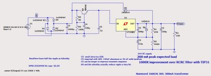
Example I am playing with
Hi ! very interested myself as well. And what the sim says ?
Thanks a lot
1. useful for preamps and especially tubes. Max current is known say 100mA.
Power Amps have already an Emitter follower in the output stage, suppressing the supply variations.
2. the reservoir caps will have a pp 100Hz ripple voltage Vr of say 1V at max current, you cannot increase their value even 10times without changing rectifier
3. the circuit will work well with a loss of 1.5V at 100mA, the 1V ripple will be reduced to <10mV pp
4. the added noise is very low, it is stable and wideband, no external feedback
5. output impedance is 1.5 ohm, not impressive but sufficient for above applications
6. few cheap parts have big effect
Last edited:
I see, why not using batteries then.Don't tell my phono pre that. It thinks it's on batteries posting a -120 db noise figure at 60 and 120hz.
Last edited:
The only benefit I see versus a regulator is tracking.
Compared to a series regulator, there is about no additional cost. The main cost is the pass transistor with it's heat sink and gear that has to be there in both cases.
So why not, go all the way to a full blown regulated PSU for low ripple, high line and load regulation, very low Zout ?
Compared to a series regulator, there is about no additional cost. The main cost is the pass transistor with it's heat sink and gear that has to be there in both cases.
So why not, go all the way to a full blown regulated PSU for low ripple, high line and load regulation, very low Zout ?
The cap multiplier is a distortion generator in the first place. It has a misleading name to say the least.
Perhaps you can explain the mechanism by which a cap multiplier distorts, generates distortion.
Cap multiplier is sooo 2017! This is what you want now:
D-Noizator: a magic active noise canceller to retrofit & upgrade any 317-based V.Reg.
D-Noizator: a magic active noise canceller to retrofit & upgrade any 317-based V.Reg.
Don't people ever use their ears? Apart from listening to noise and hum?
How hard is to listen comparatively to a passively RC filtered supply vs a passively LC filtered vs a cap multiplier vs a series reg vs a shunt reg?
One can learn so much more about the up and down sides from such a simple experiment. Like a thousand times more than from this thread
How hard is to listen comparatively to a passively RC filtered supply vs a passively LC filtered vs a cap multiplier vs a series reg vs a shunt reg?
One can learn so much more about the up and down sides from such a simple experiment. Like a thousand times more than from this thread
How hard is to listen comparatively to a passively RC filtered supply vs a passively LC filtered vs a cap multiplier vs a series reg vs a shunt reg?
It's not easy -- you have to remove all the biases which the listeners may be subject, and you have to remove your own biases and prejudices.
When we (a group of folks) did the Regulator Bakeoff, one of the factors which gave me confidence in the listening result was the that the Jung/Didden SR and Per Anders "Sjostrom" ranked at the top -- these are quite similar designs with PA paying a bit more attention to layout.
There is a widespread, deeply entrenched, almost ineradicable misbelief that regulation accuracy brings low signal distortion. And you know where it comes from. There is no shortage of voltage regulators, current regulators, current mirrors and accurate clocks with harmful impact on amplifier transfer characteristics.
A topology that rejects unwanted AC components also rejects signal components. It is not at all easy to mitigate the switching bursts produced by rectifying diodes.
There is nothing wrong with precision, but it`s inferior. The problem is that the medicine kills the patient. There are more important but neglected issues to focus on.
If I was a manufacturer constantly looking for convenient and cheap implementations, I would surely use integrated circuits.
- Status
- This old topic is closed. If you want to reopen this topic, contact a moderator using the "Report Post" button.
- Home
- Amplifiers
- Power Supplies
- So what is the down side of a cap multiplier?