What happens when the diodes block?
The junction was full of charge carriers, which get pushed out in the opposite direction, when the voltage across is negative. A burst of charge is pushed into the transformer
It charges the small stray inductance of the transformer (electrically in parallel with the secondary) and flows into the other diode' capacitance back and forth with high frequency(300kHz+), the diodes have only 20pF.
The same current is also capacitivly coupled into the rails.
A 22n cap across the diodes will not change the current burst, but lower the frequency from 300k to 9k is that better?
Or take diodes with low trr (reverse recovery time)
Schottky diodes have a very thin juction and no charge injection
Very effective a resistor in parallel with the secondary, with 3% of the regular load current, close to the diodes.
a 10n cap as close to the diodes as possible across the output rails.
Last edited:
Perhaps a reality check - the junction of a typical ss diode in a small ss or valve amplifier that is mains powered is depleted of charge and blocks voltage over a duration of time of microseconds, and where the diode experiences a change in dI/dt of the order of many mA/us. At those levels there is a vanishingly small level of reverse recovery in a diode like a 1N4002, and an even lesser level if a fast diode is used.
The only 'burst of charge' is the energy in the secondary winding leakage inductance during the turn-off duration, which forces a dV/dt step in the secondary winding voltage waveform that tries to keep the diode conducting if it can't find other exit paths (such as to stray winding capacitance or a snubber in parallel to the winding). Adding a capacitor in parallel to the diode just makes it a snubber, whereby the blip of energy finds it easier to 'take the long way around' via typically the first filter cap in what can be a relatively larger loop area, and with common sections of wiring (including the ESL of the main filter capacitor) that can couple the transient to load circuitry and beyond.
The level of energy in the secondary winding leakage inductance, and the duration over which it can dissipate, is very dependant on the diode current conduction duration and peak level - which some people forget about when they just add on more and more filter capacitance for no net benefit.
Last edited:
That is important. Inductances do not like current switch off.dV/dt step in the secondary winding voltage waveform that tries to keep the diode conducting


nigelwright7557, given that literally millions of valve type equipment have been made with 1N4007 type rectifiers, I'd suggest it was your custom deployment that was the issue wrt buzzing, rather than the use of 1N4007 per se.
Thats not what I found.
Nothing custom about a transformer, full wave rectifier and smoothing.
Problem was fixed with HER158G's.
The switching spikes were very narrow but still came through on audio as buzz.

Last edited:
nigelwright7557, my point was that there is nothing custom about all the other valve gear that have used 1N4007, but there is something custom about your amp - you implemented those parts and everything around it in such a way as to generate a buzz - that's a key aspect about the difference between a simulation and reality where inadvertent coupling from custom layout and part connections can sometimes make a big and buzzing difference.
You guys are madly OT in most cases. Please read the original question and answer it. Bear in mind the OP's level of experience, likely equipment available, and answer his question which was about restoring an old transistor radio.
Were I him I would have run screaming from this thread a couple of days ago..
Were I him I would have run screaming from this thread a couple of days ago..
Do you have any simple AM radio?Using 4 components in place of 8 sounds like a good deal to me, probably with better results.
Hello and thanks everyone for their contribution.I replaced the original diodes with 1N4007 and 22nF/63V ceramic disc capacitors in parallel with each diode and everything is ok.
My next concern is with my cdplayer Denon-DCD625.I replaced all electrolytics with low ESR.
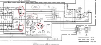
C511,C512,C513 are not used on pcb but the pads are there.What values should i use for these caps?
Can i replace original diodes D501-D504 1SR35 with shottky SB1100 as i already have them in my parts?
What can i use for D505,D506?Voltage at the anode of D506 is 50V with no disc playing.
My next concern is with my cdplayer Denon-DCD625.I replaced all electrolytics with low ESR.
C511,C512,C513 are not used on pcb but the pads are there.What values should i use for these caps?
Can i replace original diodes D501-D504 1SR35 with shottky SB1100 as i already have them in my parts?
What can i use for D505,D506?Voltage at the anode of D506 is 50V with no disc playing.
Attachments
Last edited:
Ok, but it can depend a bit. It can be better (more safe), in general, to use general use type electrolytics.My next concern is with my cdplayer Denon-DCD625. I replaced all electrolytics with low ESR.
If we are talking about C507, 508, 509, 510 - they have quite a low capacity (size) so their ESR is quite high enough even if they are Low ESR (I mean it wan't be too low in the case of use of a low-ESR type).
Use a low-ESR C501, C502 may worsen a situation with a 100 Hz harmonics if PCB is wired badly. May not, if PCB is wired fine.
It is better to place RC-snubbers there (across the secondaries), but not only caps. At least in the one most loaded secondary. Only caps will resonate a bit, so I can't say exact value to place.C511,C512,C513 are not used on pcb but the pads are there.What values should i use for these caps?
Yes.Can i replace original diodes D501-D504 1SR35 with shottky SB1100 as i already have them in my parts?
I'm not sure about a purpose of this circuit (why it is two diodes in series here), so I would rather use the same type as 1SR35 here - usual silicon rectifier diodes, e.g. 1N4007.What can i use for D505,D506? Voltage at the anode of D506 is 50V with no disc playing.
Last edited:
- Status
- This old topic is closed. If you want to reopen this topic, contact a moderator using the "Report Post" button.
- Home
- Amplifiers
- Power Supplies
- Capacitors across rectifier diodes