Hello
This is my first post on this forum. I'm not an electronics worker just a hobbyist. I know English at a basic level, so please be understanding.
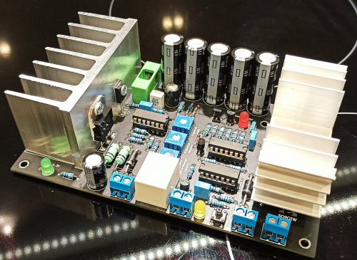
I would like to introduce you to a tube amplifier power supply that I am currently building. All modules are already running and tested.
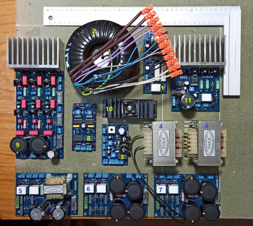
1. Transformer soft start.
2. Everyone knows
3. A 12 V auxiliary voltage power supply and fans' power supply.
4. Chokes.
5. Rectifier for preamplifier and tone regulator.
6. Rectifier of the right channel amplifier.
7. Rectifier of left channel amplifier.
8. Rectifier start - "controller".
9. Triple adjustable voltage stabilizer (430 V; 430 V; 260 V).
10. And everyone knows again.
11. Tube heater power supply 6,3 V with soft start.
The next step that awaits me now is to pack all these modules into one housing with two fans.
Sample housing.
Obudowa PESANTE 2U - 1NPS02400N - panel 10mm - CZARNY - Sklep modushop.pl
Sample fans.
NF-A6x25 FLX
If the topic will interests you I will be happy to provide details.
Jurek.
This is my first post on this forum. I'm not an electronics worker just a hobbyist. I know English at a basic level, so please be understanding.
I would like to introduce you to a tube amplifier power supply that I am currently building. All modules are already running and tested.

1. Transformer soft start.
2. Everyone knows
3. A 12 V auxiliary voltage power supply and fans' power supply.
4. Chokes.
5. Rectifier for preamplifier and tone regulator.
6. Rectifier of the right channel amplifier.
7. Rectifier of left channel amplifier.
8. Rectifier start - "controller".
9. Triple adjustable voltage stabilizer (430 V; 430 V; 260 V).
10. And everyone knows again.
11. Tube heater power supply 6,3 V with soft start.
The next step that awaits me now is to pack all these modules into one housing with two fans.
Sample housing.
Obudowa PESANTE 2U - 1NPS02400N - panel 10mm - CZARNY - Sklep modushop.pl
Sample fans.
NF-A6x25 FLX
If the topic will interests you I will be happy to provide details.
Jurek.
Hello again and sorry for the long absence.
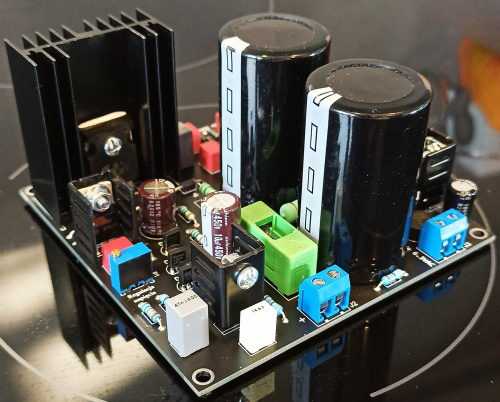
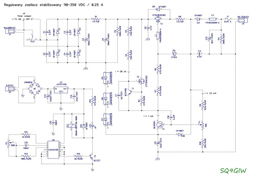
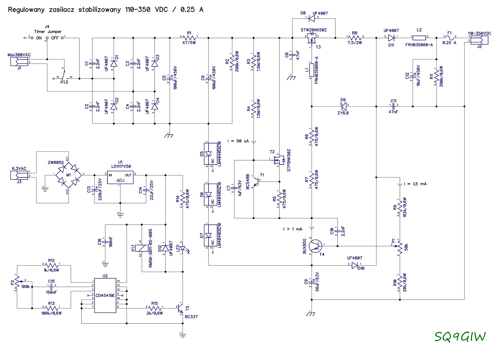
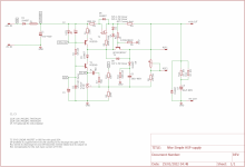
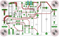
Today I would like to discuss a less complicated project. It is a stabilized power supply with adjustable output voltage from 110 to 350 VDC / 250 mA.
The regulated power supply is intended for supplying systems and devices requiring voltage in the range from 110 V to 350 V. In particular, for supplying all types of systems built with the use of electron tubes. The output voltage is stabilized and perfectly filtered, which translates into the absolute absence of hum and other interference from the 230 V mains in the loudspeaker sets. Thanks to very precise voltage stabilization, the tubes work constantly in comfortable conditions, in exchange for great sound. Additionally, such a power supply significantly facilitates the start-up and measurements of the constructed tube device. To prevent current surges, the power supply performs a soft start function immediately after being turned on. The time of voltage rise at the output of the power supply from 0 V to the voltage set with a precise multi-turn potentiometer is about 1.5 - 2 seconds. The power supply is also protected against short-circuits and overloads that may occur, for example, during construction and commissioning of a tube amplifier. In addition, we also have a delayed switching of the anode voltage in relation to the filament supply, which we can supply directly from the transformer winding designed for 6.3 VAC incandescence. In the finished device with the above-mentioned stabilized power supply, the lamps work all the time in comfortable conditions, which also has a positive effect on their service life. The power supply is also protected against short-circuits and overloads that may occur, for example, during construction and commissioning of a tube amplifier. In addition, we also have a delayed switching of the anode voltage in relation to the filament supply, which we can supply directly from the transformer winding designed for 6.3 VAC incandescence. In the finished device with the above-mentioned stabilized power supply, the lamps work all the time in comfortable conditions, which also has a positive effect on their service life. The power supply is also protected against short-circuits and overloads that may occur, for example, during construction and commissioning of a tube amplifier. In addition, we also have a delayed switching of the anode voltage in relation to the filament supply, which we can supply directly from the transformer winding designed for 6.3 VAC incandescence. In the finished device with the above-mentioned stabilized power supply, the lamps work all the time in comfortable conditions, which also has a positive effect on their service life.
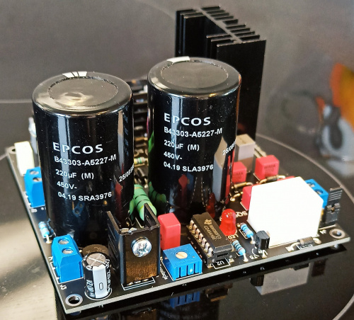
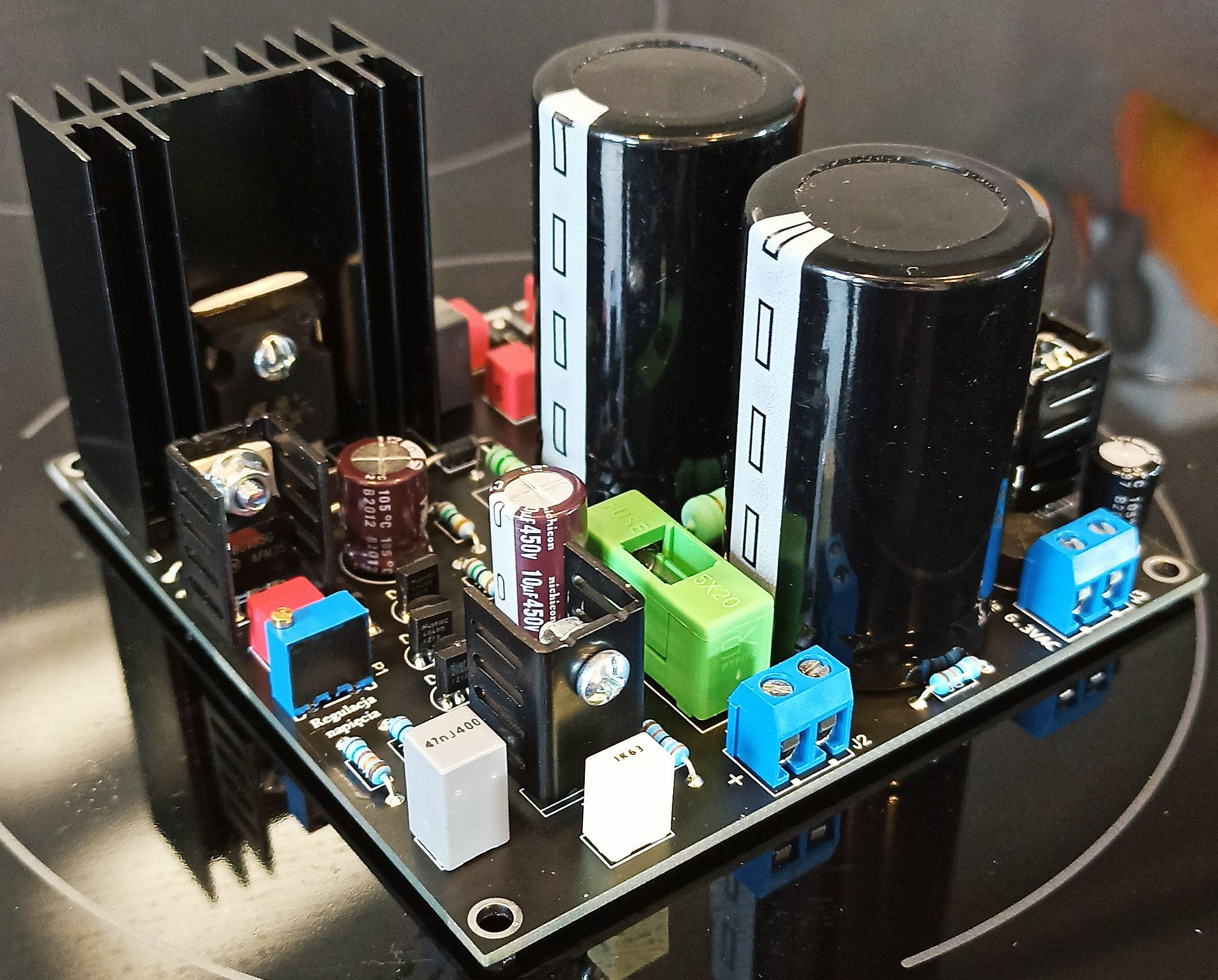
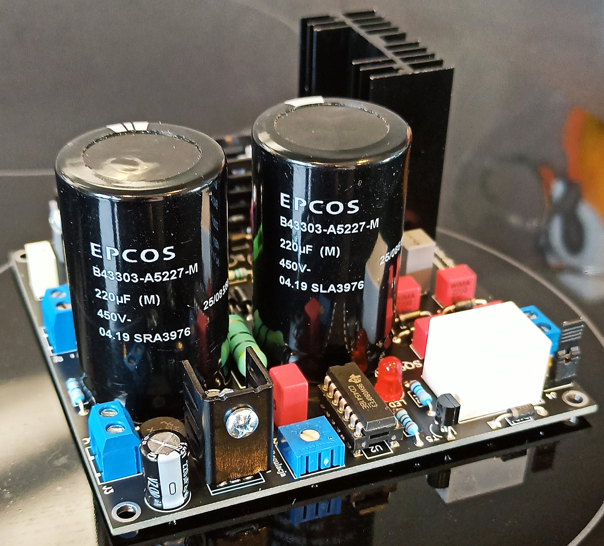
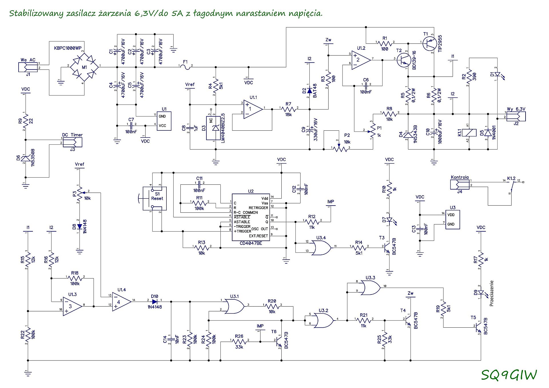
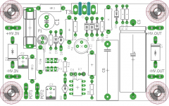
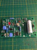
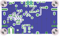
And here we have a power supply for heaters for 6.3 VDC / 5 A vacuum tubes with a slow voltage rise. Both power supplies can cooperate with each other.
Technical data:
Output voltage: 6.3V (6-7V adjustable)
Output current: up to 5 A (1-5.5 A adjustable protection)
Overload protection reaction: 75 μs (0.000075 s)
Complete short-circuit resistance of the output terminals
Input voltage: 9 Vac for I ≤ 3 A or 10 Vac for I> 3 A
Voltage rise time: 35s to 6.3V (7V).
Over voltage protection: 7.5V
Ripple at 5 A Uwe = 10 Vac: 250 μVrms (0.00025 Vrms)
Ripple at 3 A Uwe = 9 Vac: 200 μVrms (0.002 Vrms)
Power stage heat sink temperature: max 95 ° C at Iobc = 5 A Uwe = 10 Vac Uwy = 6.4 V
Power stage heat sink temperature: max 70 ° C at Iobc = 3 A Uwe = 9 Vac Uwy = 6.4 V
Bridge rectifier heat sink temperature: max 85 ° C at Iobc = 5 A
Bridge rectifier heat sink temperature: max 60 ° C at Iobc = 3 A
Cooperation with the HV anode power supply
Dimensions: 150 x 90 x 55 mm.
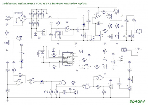
Complete documentation of both power supplies is attached. Documentation is in Polish. But don't worry, just paste the text into google translator. And everything will become clear.
Regards.
Jurek.
Yes, I design everything myself.I'm listening.
Where do you get the modules ? Or du you make them yourseldf ?
Today I would like to discuss a less complicated project. It is a stabilized power supply with adjustable output voltage from 110 to 350 VDC / 250 mA.
The regulated power supply is intended for supplying systems and devices requiring voltage in the range from 110 V to 350 V. In particular, for supplying all types of systems built with the use of electron tubes. The output voltage is stabilized and perfectly filtered, which translates into the absolute absence of hum and other interference from the 230 V mains in the loudspeaker sets. Thanks to very precise voltage stabilization, the tubes work constantly in comfortable conditions, in exchange for great sound. Additionally, such a power supply significantly facilitates the start-up and measurements of the constructed tube device. To prevent current surges, the power supply performs a soft start function immediately after being turned on. The time of voltage rise at the output of the power supply from 0 V to the voltage set with a precise multi-turn potentiometer is about 1.5 - 2 seconds. The power supply is also protected against short-circuits and overloads that may occur, for example, during construction and commissioning of a tube amplifier. In addition, we also have a delayed switching of the anode voltage in relation to the filament supply, which we can supply directly from the transformer winding designed for 6.3 VAC incandescence. In the finished device with the above-mentioned stabilized power supply, the lamps work all the time in comfortable conditions, which also has a positive effect on their service life. The power supply is also protected against short-circuits and overloads that may occur, for example, during construction and commissioning of a tube amplifier. In addition, we also have a delayed switching of the anode voltage in relation to the filament supply, which we can supply directly from the transformer winding designed for 6.3 VAC incandescence. In the finished device with the above-mentioned stabilized power supply, the lamps work all the time in comfortable conditions, which also has a positive effect on their service life. The power supply is also protected against short-circuits and overloads that may occur, for example, during construction and commissioning of a tube amplifier. In addition, we also have a delayed switching of the anode voltage in relation to the filament supply, which we can supply directly from the transformer winding designed for 6.3 VAC incandescence. In the finished device with the above-mentioned stabilized power supply, the lamps work all the time in comfortable conditions, which also has a positive effect on their service life.
And here we have a power supply for heaters for 6.3 VDC / 5 A vacuum tubes with a slow voltage rise. Both power supplies can cooperate with each other.
Technical data:
Output voltage: 6.3V (6-7V adjustable)
Output current: up to 5 A (1-5.5 A adjustable protection)
Overload protection reaction: 75 μs (0.000075 s)
Complete short-circuit resistance of the output terminals
Input voltage: 9 Vac for I ≤ 3 A or 10 Vac for I> 3 A
Voltage rise time: 35s to 6.3V (7V).
Over voltage protection: 7.5V
Ripple at 5 A Uwe = 10 Vac: 250 μVrms (0.00025 Vrms)
Ripple at 3 A Uwe = 9 Vac: 200 μVrms (0.002 Vrms)
Power stage heat sink temperature: max 95 ° C at Iobc = 5 A Uwe = 10 Vac Uwy = 6.4 V
Power stage heat sink temperature: max 70 ° C at Iobc = 3 A Uwe = 9 Vac Uwy = 6.4 V
Bridge rectifier heat sink temperature: max 85 ° C at Iobc = 5 A
Bridge rectifier heat sink temperature: max 60 ° C at Iobc = 3 A
Cooperation with the HV anode power supply
Dimensions: 150 x 90 x 55 mm.

Complete documentation of both power supplies is attached. Documentation is in Polish. But don't worry, just paste the text into google translator. And everything will become clear.
Regards.
Jurek.
Attachments
Last edited:
Hi Jurek, rectifier commutation noise may be a concern. It may be a benefit to use a CRC snubber located at the power transformer, and to remove the caps you have put in parallel with the diodes, as a way to localise such noise to effectively the transformer secondary winding.
How does the heater supply respond to initial overload - by hiccupping?
How does the heater supply respond to initial overload - by hiccupping?
How does the heater supply respond to initial overload - by hiccupping?
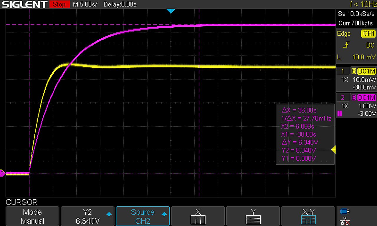
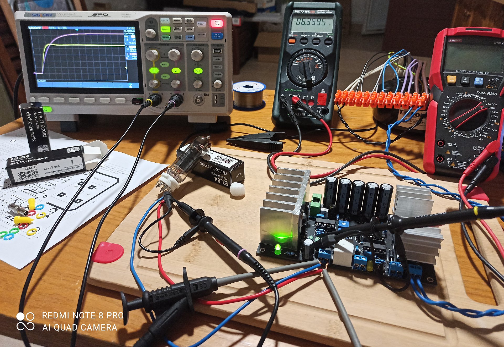
Thank you for the important question. My target was to make a stabilizer that does not get hiccups regardless of the load.
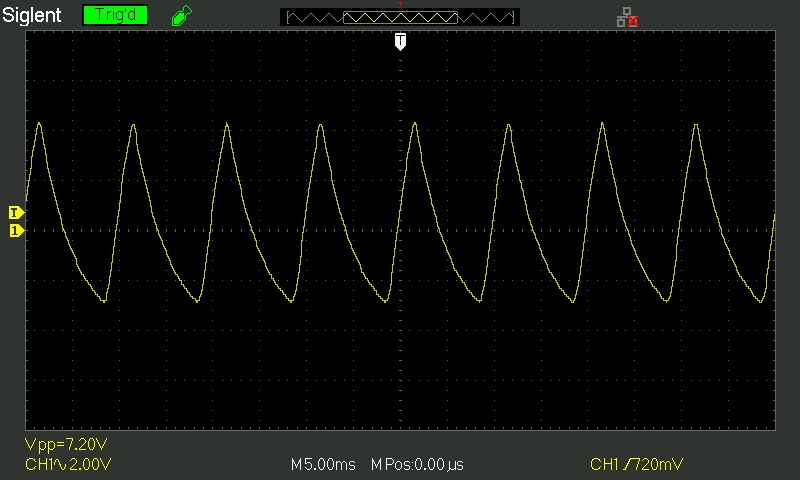
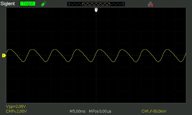
In the oscillogram below you can see the start of the power supply loaded with the EL84 heater. The purple waveform is voltage and the yellow waveform is heater current EL84. The heater current was obviously indirectly measured. The yellow oscilloscope probe was connected to R5; R6.
Hi Jurek, rectifier commutation noise may be a concern...
No noise
")
Measurement on C5 - load 108 mA.
Measurement on C6 - load 108 mA.
Last edited:
Jurek, the better test may be to start up with a nominal 4 to 4.5A heater load, and see if the ramped voltage is sufficient to keep the heater current below 5A, or if it does reach 5A then whether there is any operational concern.
Rectification noise may enter the audio chain in a variety of ways, so a clean power supply rail may be only the start of testing.
Rectification noise may enter the audio chain in a variety of ways, so a clean power supply rail may be only the start of testing.
Ive designed a similar regulator, but took the TL431 for the control chip. attached all the design files, in case you want to do anything with it.
Attachments
- Home
- Amplifiers
- Power Supplies
- Tube amplifier power supply