In the last week my stereo SE PCL82 kitchen amp developed 100Hz hum after >1 year of solid use, sometimes many hours a day. I'm looking for some guidance on likely causes / troubleshooting methods before I fall down a rabbit hole of trial-and-error despair!
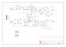
Schematic attached.
Symptoms:
The LT regulator supplies 0.6A @ ~14-15VDC.
My initial thought is to replace the HT MOSFET Q2 and regulator U2 - as if there was any failure to regulate properly, the ripple on the HT would pass from plate -> speaker.
Any ripple on the LT side might be less audible - like normal AC heaters?
If it is a temperature-related failure, freeze-spraying should show that up? Or would cooling the component cause other issues?
I'm slightly nervous of scoping the HT line given it is close to 300V (which I think is the limit on my scope's input). But I do have 1000:1 probes if that would help spot where the problem starts.
Basically, I'd be grateful for suggestions of a methodical approach to fault diagnosis, Pease-style.
Schematic attached.
Symptoms:
- 100Hz hum (verified by basic FFT) in both channels starting a couple of minutes after power is applied.
- Normal audio heard prior
- System otherwise normal
- This is my PCB based on a design by Merlin that has been used successfully by others.
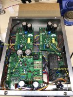
- I had an issue with thermals - without heatsinking (or even with it on very hot days) an audible 'throbbing' would occur intermittently. I moved the MOSFET and LT regulator to opposite sides of the chassis, with external heatsinks attached.
- Has worked (other than the throbbing on hot days) for over a year without trouble.
- Visual check of PS caps - no bulging
- Visual check of off-board connections to the MOSFET / LT Regulator - all seemingly OK
- Replacement of valves with a new set - no change
- Scope
- Multimeter
- Freeze spray
The LT regulator supplies 0.6A @ ~14-15VDC.
My initial thought is to replace the HT MOSFET Q2 and regulator U2 - as if there was any failure to regulate properly, the ripple on the HT would pass from plate -> speaker.
Any ripple on the LT side might be less audible - like normal AC heaters?
If it is a temperature-related failure, freeze-spraying should show that up? Or would cooling the component cause other issues?
I'm slightly nervous of scoping the HT line given it is close to 300V (which I think is the limit on my scope's input). But I do have 1000:1 probes if that would help spot where the problem starts.
Basically, I'd be grateful for suggestions of a methodical approach to fault diagnosis, Pease-style.
Attachments
That this happens after a few minutes can point to a "leaky " capacitor it does not need to bulge the casing that's when it gets worse .
Looking at the diagram I would check out =C7/6 and the smaller electrolytic capacitors , you said overheating occurred including pulsing on a hot day which is capacitor linked noise less likely to be overheating resistors .
I would leave the freeze spray out of it just now its good for isolating large TV PCB faults and other equipment but in an already hot unit it could change values of components quickly not always to the good.
If your probes are 1000 : 1 it should be okay if they are quality ones , I only use 10: 1 probes but I have an old CRT scope not a fully digital LCD one and can measure (P/P) much higher voltage waveforms .
I set the system up today and dedicated some time to observe afresh. I kept the bottom panel off the chassis to let air circulate etc.That this happens after a few minutes can point to a "leaky " capacitor it does not need to bulge the casing that's when it gets worse .
The hum/buzz came up just as the valves warmed up. But, strangely, disappeared for a period, then came back intermittently for a period (10-15 mins) before becoming a permanent presence.
That's interesting. C7/6 are the heater side of the system. Would C12 be the equivalent on the HT side? It makes sense that overheating could mess with the electrolytics. And simple enough to replace.Looking at the diagram I would check out =C7/6 and the smaller electrolytic capacitors , you said overheating occurred including pulsing on a hot day which is capacitor linked noise less likely to be overheating resistors .
Could hum come in from the DC heater supply? Guess this is something I could scope to look for ripple that shouldn't be there, safely.
So a 1st step might be to temporarily use a new IRF820 for Q2. Then a new LM317 for U1. [If MOSFETs would fail like this...] Then replace the caps.
Noted. I'll put it away!I would leave the freeze spray out of it just now its good for isolating large TV PCB faults and other equipment but in an already hot unit it could change values of components quickly not always to the good.
A sloppy typo on my front. Apologies. I meant 100:1. My digital scope is a Rigol - I was never sure that these probes meant I could probe HT lines at will...If your probes are 1000 : 1 it should be okay if they are quality ones , I only use 10: 1 probes but I have an old CRT scope not a fully digital LCD one and can measure (P/P) much higher voltage waveforms .
Very strange, but I think resolved.
I scoped the HT and heater test points. There was some lovely ripple on the HT side. But I also noticed the HT output level was >300VDC and beyond what I had intended. Altering the trim pot I reduced the HT to ~280V and with it reduced the ripple to practically zero.
Not sure how that could have happened - but I'll check the state of the trim pot periodically.
Glad it fixed itself.") But alas, I've been trying to talk myself out of posting this for a couple hrs -- there are far too many people on this site more knowledgeable and experienced with LM317's than me. Aww, what the hay? How much is one more chance at looking foolish gonna hurt?
But alas, I've been trying to talk myself out of posting this for a couple hrs -- there are far too many people on this site more knowledgeable and experienced with LM317's than me. Aww, what the hay? How much is one more chance at looking foolish gonna hurt?
There appear to be a couple of capacitors missing. Your U2 needs a 0.1uF capacitor to ground at its input terminal for stability. The chassis-width-long wires connecting the MOSFET virtually guarantee it.
Assuming Q2 is supposed to be a 'capacitor multiplier' -- it needs a capacitor! Pretty sure the capacitance of a pair of 1N4007's and two 12V zeners won't give the desired effect.
Also, the trimpot will be more reliable (especially over years) if it is between the Out and Adj legs. That way any intermittence will decrease the output voltage, rather than increase it.
Not sure if these mods will remedy all the symptoms you described, but they're considered good practice anyway.
Cheers
But alas, I've been trying to talk myself out of posting this for a couple hrs -- there are far too many people on this site more knowledgeable and experienced with LM317's than me. Aww, what the hay? How much is one more chance at looking foolish gonna hurt?There appear to be a couple of capacitors missing. Your U2 needs a 0.1uF capacitor to ground at its input terminal for stability. The chassis-width-long wires connecting the MOSFET virtually guarantee it.
Assuming Q2 is supposed to be a 'capacitor multiplier' -- it needs a capacitor! Pretty sure the capacitance of a pair of 1N4007's and two 12V zeners won't give the desired effect.
Also, the trimpot will be more reliable (especially over years) if it is between the Out and Adj legs. That way any intermittence will decrease the output voltage, rather than increase it.
Not sure if these mods will remedy all the symptoms you described, but they're considered good practice anyway.
Cheers
Last edited:
I wouldn't disagree with most of what you say especially long cabling for the mosfets almost guarantees insipid oscillation I never had more than an inch from the gates to the PCB.
A Mosfet designer in EW gave a detailed technical graph of each added inch,s effect on HF oscillation /instability several decades ago.
A Mosfet designer in EW gave a detailed technical graph of each added inch,s effect on HF oscillation /instability several decades ago.
Back in September I spoke too soon - the hum came back shortly after my last post. It's taken me until today to do something about it.
I thought I had this covered moving the breakout resistors to my daughter board for Q2. Evidently not.
Today I brute-forced a solution by adding a ferrite bead to each wire connecting the Q2 daughter board. After an hour or so of use the hum hasn't returned.
I'll report back in case anyone has a similar issue in the future.
I wouldn't disagree with most of what you say especially long cabling for the mosfets almost guarantees insipid oscillation I never had more than an inch from the gates to the PCB.
A Mosfet designer in EW gave a detailed technical graph of each added inch,s effect on HF oscillation /instability several decades ago.
I thought I had this covered moving the breakout resistors to my daughter board for Q2. Evidently not.
Today I brute-forced a solution by adding a ferrite bead to each wire connecting the Q2 daughter board. After an hour or so of use the hum hasn't returned.
I'll report back in case anyone has a similar issue in the future.
Thank you Tristanc for reporting back on this --not everyone does .
I agree its "brute force " while others welcome adding ferrite beads I am in a minority of probably 1 in never using them I prefer to use circuit layout/design to cure my problems of this sort .
Of course it takes much longer but I have the patience to do this.
I did notice --and sorry I did not mention it before but could you try adding a filter capacitor at the input and output to the values as outlined on this upmarket Electrical Engineers website .
I know full well cries of--- "you don't need them" will ensue , I always fit them and have done since they first came on the market .
Its just a test but if you are still having this problem then all bases must be touched .-
voltage regulator - LM317 circuit capacitor question - Electrical Engineering Stack Exchange
I would suspect a slight problem with the layout but try that anyway .
So the hum returned soon after my last post and the ferrites made no difference.
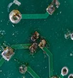
This morning I took the amp apart and observed the attached scene on the bottom of the PCB - this is the LM317. Looks like it got quite hot.
I've removed the existing LM317, cleaned up as best I can, checked for continuity, and installed a replacement. I soldered both sides of the PCB as I noticed the pads on the rear have lifted a bit.
Re-assembling and testing - the hum is gone. Perhaps this was the issue all along - a fried LM317 or bad soldering on my part...
Let's see what happens.
Thanks for the other comments on the schematic / design. I'll keep that in mind in case I need to get a new PCB made up.
Tristan
Attachments
As I said in post #7, where is the output capacitor on the LM317 ??? -- you need at least 47u to 100uF aluminum electrolytic to maintain stability of any LM317 regulator.
From the photographs it would appear that the leads to the mosfet pass device are much too long -- another reason for instability.
The zener diode protecting the gate of the MOSFET should be connected directly to the gate, not via 100R.
How did you determine the R and C values for the snubber? These depend on the transformer you're using. Mark Johnson's Quasimodo jig -- the cheap modo -- will get you the right answer very quickly.
It will work for a while, then destroy itself.
Last edited:
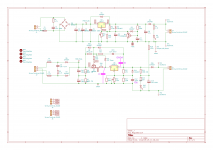
I've sketched up the suggested changes, attached. C_i = A, C_o = B.As I said in post #7, where is the output capacitor on the LM317 ??? -- you need at least 47u to 100uF aluminum electrolytic to maintain stability of any LM317 regulator.
You suggest C_o=47u-100u. I see elsewhere that C_i could be ~0.1u. And then C_adj = 10u
I'll look at how I could insert those.
Agreed - bad planning on my part on the thermals... The stoppers are where they should be located - I had hoped that, with the ferrites, would assist in preventing oscillation.From the photographs it would appear that the leads to the mosfet pass device are much too long -- another reason for instability.
This design is from Merlin - he talks it through in his hifi preamp book, so I blindly copied.The zener diode protecting the gate of the MOSFET should be connected directly to the gate, not via 100R.
Likewise - these are 'general' values from Merlin's design. Likely make no audible difference in this particular use case (single ended 1W kitchen radio).How did you determine the R and C values for the snubber? These depend on the transformer you're using. Mark Johnson's Quasimodo jig -- the cheap modo -- will get you the right answer very quickly.
It will work for a while, then destroy itself.
Tristan
Attachments
- Home
- Amplifiers
- Power Supplies
- Help troubleshooting Maida regulated supply