Well, that is a highly optimistic simulation. As it turns out L1 from AoEX9 must have been an air-wound inductor!
Experiments with an LTC active filter driven by a couple sections of a CMOS hex inverter were very encouraging and probably much less expensive than the passive components. Pix tomorrow.
Experiments with an LTC active filter driven by a couple sections of a CMOS hex inverter were very encouraging and probably much less expensive than the passive components. Pix tomorrow.

Hi Jack, the latest sine wave inverters are class D, PWM cheap and nasty but works really, really well. Using a class B amp you will dissipate twice the power on the system. The class D only dissipates during the rise and fall time of the square wave. Thus, a generator such as what you suggest is perfect,
Add two or more (depend on your consumption) mosfets and a PWM chip can be made for pocket change.
Obviously you want to run it on high voltage which would save you the cost of an expensive lump of steel and copper due to the high frequency operation.
If you want to just play around using a step up transformer you can and does not really matter where the step up or down takes place it is purely a matter of cost even, use of a high current inductor is the way to go but you may even get away using the output transformer, it may run a bit hot because it is not made for high frequency components, the idea is to fool around and look, it is straight forward when you think if it. its inductance as part of your low pass filter and then the need for a large high current coil on the output become less of an issue.
It is all about economics the THD of a class D amp is miniscule and orders of magnitude below that of your incoming mains....
Use your 1000watt in car stereo and your oscillator with a transformer, a signal generator app on your phone and the amp is about all you need to start your fooling around, then you can go and custom design around the needs and what is in your junk box.
Last edited:
BTW in the amp PWM chip everything is done. Even the "complex" output drivers that should never overlap. You're very good Chinese friend offers a PWM PCB used in almost every sine wave inverter for fewer bucks than one beer., they work really well All you need to add is your high voltage Mosfets, heat sinks and your highly skilled motherboard. There will be enough fun in it, it would be almost as complex as your least complex amplifier output stage you ever made.
It features over voltage under voltage frequency stability, sort circuit, start-up ramp, you name it, it is there. It is probably a crib of a Yank design anyway, most likely On Semi, Ti just search for UPS/Inverter or something to get the original chip, I forget the Chinese part number and manufacturer, they are normally scraped off in-case custom officials block them. Saves you doing a lot of head scratching regulating, feedback, low THD and more. All obvious and would not make you any worse a designer, just a short-cut to what you already know or thinking about.
Have much fun!!!
Last edited:
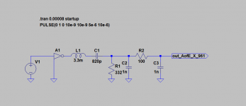
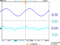
Probably some diode switching noise on the output -- just a simple CRC 10u_10R_10u filter on the output:
Good God how did you come up with that project name, I think circuit1,sch would have been okay. Must have taken you more time to dream up the name than designing it

Sh!t, I should make use if spell checked before posting anything, I almost always have to go back and edit my posts.
Last edited:
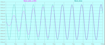
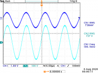
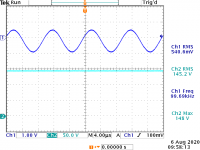
Note that the amplifier is operating at 100kHz. This is the optimal frequency for the transformer at hand, and high enough not to be a bother at audio. I had thought of PWM but 20kHz won't work.
I have on hand some slew controllable PWM chips which are more efficient, but as the wave becomes more "sine-like" power consumption and heat go up.
I replaced CRC with CLC -- 100uH -- still a 30mA load:
I have on hand some slew controllable PWM chips which are more efficient, but as the wave becomes more "sine-like" power consumption and heat go up.
I replaced CRC with CLC -- 100uH -- still a 30mA load:
Attachments
You obviously want to make a super-quiet supply.
Starting with a quiet base waveform looks like a no-brainer, but is it actually the best strategy?
If you use a conventional peak rectified supply, there is no way the sine arches are going to fit into a straight line: this means discontinuities, thus switching noise.
An alternative strategy is to use suitable waveforms: trapezoidal for example.
They provide controlled transitions and a flat top.
Another possibility is to use a super clean sinewave, and not damage it during the rectification process.
A way to achieve that is to use a large inductor after the rectifier: the diodes will remain ON all the time, and the input waveform won't be distorted.
The generation itself can be made in a less expensive manner: a Royer converter for example has a good output purity.
Class E converters can also provide a good purity
@Elvee -- I was a bit put off by Williams comments in AN-118 wrt the Royer's noise components, so did not (reflexively) choose that route but in my naivete did not fully appreciate that the inductor would keep the diodes conducting. Thanks for pointing this out. Your comments are most welcome!
The trapezoid -- easily clamped triangle oscillator --
It's very easy to get a 48VDC wall-wart, and experimenting with the LT1683 "jig" I can get a variety of transformer and inductance values which will hit the target voltage under the load conditions I anticipate.
Thanks! Jack
The trapezoid -- easily clamped triangle oscillator --
It's very easy to get a 48VDC wall-wart, and experimenting with the LT1683 "jig" I can get a variety of transformer and inductance values which will hit the target voltage under the load conditions I anticipate.
Thanks! Jack
- Status
- This old topic is closed. If you want to reopen this topic, contact a moderator using the "Report Post" button.
- Home
- Amplifiers
- Power Supplies
- Regeneration for a very quiet tube power supply