I made a little smoky smell with my ESP power supplies today, which did not make me happy.
I need a -5V / 0V / +5 power supply for my PGA2311 analogue side, and I also need an independent 0V / 5V power supply for the digital side.
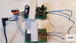
I picked Rod Elliotts P05D for the analogue power supply, as it also gives me ~13V auxiliary unregulated output to drive my source selection servos. I used Rod's P05 Mini for the 5V digital power supply - but with only the positive side components fitted. It's a bit simpler.
Both power supplies operate from the same 9V AC input, sourced from a wall-wart transformer. (18VA). I would like to keep all the mains voltage out of the preamp box.
On the 5V Mini; AC is applied to AC1 and AC2, with no connection to the GND input terminal.
On the bipolar P05D, my single AC input is connected to terminals AC2 and GND.
Now perhaps may of you have already seen where this is going... but I didnt! My 0V outputs are different! With the same AC input, the 0V outputs differ by 5.85V which is a horror show. And although I can plainly see each PS has a different architecture, I don't know how to fix it. (The 0V analogue and digital 'ground' will ultimately be joined at one point on the PCB so this different is... unacceptable).
Should I build two bipolar supplies and just ignore one of the -5V outputs? I am willing to start from scratch, the only thing I really want to keep is my external 9V AC power supply. Please please please set me straight! What is the simplest architecture to get from one AC input to the independently regulated digital/analogue supplies that I described above?
Popchops.
I need a -5V / 0V / +5 power supply for my PGA2311 analogue side, and I also need an independent 0V / 5V power supply for the digital side.
I picked Rod Elliotts P05D for the analogue power supply, as it also gives me ~13V auxiliary unregulated output to drive my source selection servos. I used Rod's P05 Mini for the 5V digital power supply - but with only the positive side components fitted. It's a bit simpler.
Both power supplies operate from the same 9V AC input, sourced from a wall-wart transformer. (18VA). I would like to keep all the mains voltage out of the preamp box.
On the 5V Mini; AC is applied to AC1 and AC2, with no connection to the GND input terminal.
On the bipolar P05D, my single AC input is connected to terminals AC2 and GND.
Now perhaps may of you have already seen where this is going... but I didnt! My 0V outputs are different! With the same AC input, the 0V outputs differ by 5.85V which is a horror show. And although I can plainly see each PS has a different architecture, I don't know how to fix it. (The 0V analogue and digital 'ground' will ultimately be joined at one point on the PCB so this different is... unacceptable).
Should I build two bipolar supplies and just ignore one of the -5V outputs? I am willing to start from scratch, the only thing I really want to keep is my external 9V AC power supply. Please please please set me straight! What is the simplest architecture to get from one AC input to the independently regulated digital/analogue supplies that I described above?
Popchops.
Attachments
Last edited:
You MUST wire both the same - with one transformer terminal to ground.
Do NOT add the link at C2. You missed Rod's warning (para 'single poliarity supplies').
The supply is then half wave rectified.
However, for digital supply, a cheap Ebay buck regulator would be more efficient (less heat). Transformer, single diode in +ve line, smoothing cap, buck regulator.
You are regulating 13V down to 5V so calculate the regulator dissipation.
13-5 = 8.
8V x current = power dissipated in regulator.
Amazing. Thanks. Glad you mentioned the extra link.
I shorted across the unused inputs, same on both boards and it worked fine.
I'm a bit worried that I've damaged something as the idle current on the positive side (across R1) is approx 50% more than on the negative side.
Regulated voltages are bang on target though, and 0V outputs match exactly.
Thanks russc.
- Status
- This old topic is closed. If you want to reopen this topic, contact a moderator using the "Report Post" button.