I’m a learner and posting here again becauno answer earlier (and jumpy inguess)..
se i’ve tried to google for the “issue” I have and not found anything, and really wanna solve this. so here it goes;
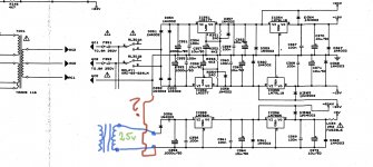
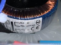
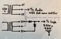
In my Nad 116I added an extra PT (actaully 2 new transformers of 2x25v sec and the one for audio section slightly larger) for logics and what i can understand this is a half wave rectifier curcuit for logic supply but is this correct how to implent a second transformer?
The whole mainboard share the same “ground” and the audio section has its centertap to this “ground” but will there be issues if i use the same “ground” for the new pt? So basically same “ground” for both pt’s? Or does the ground or zero or what we call it need to be separated?
See my drawing please. The smaller PT i’ve paralleled to give 1x25v.
I’ve also added an extra fuse on that new pt but unsure what right fuse will be. Current draw over the 2.2R fusible res was max 100ma. But this currentdraw only count what the 7805 draw or? Not total?
Added a input mainfuse also to new PT and its now about 250ma. There was only those 2x800ma on the secondary before.
I’m guessing now that they are too big now when the load isn’t that big over that part of the curcuit anymore.
I’ve tried and look for answer also how i can measure currentdraw from each curcuit so i can fuse them properly.
Everything is hooked up and using only one rectifier diod now.
Just lack the courage to push the button because it feels somehow wrong what i’ve done.
Thx for your help.
se i’ve tried to google for the “issue” I have and not found anything, and really wanna solve this. so here it goes;
In my Nad 116I added an extra PT (actaully 2 new transformers of 2x25v sec and the one for audio section slightly larger) for logics and what i can understand this is a half wave rectifier curcuit for logic supply but is this correct how to implent a second transformer?
The whole mainboard share the same “ground” and the audio section has its centertap to this “ground” but will there be issues if i use the same “ground” for the new pt? So basically same “ground” for both pt’s? Or does the ground or zero or what we call it need to be separated?
See my drawing please. The smaller PT i’ve paralleled to give 1x25v.
I’ve also added an extra fuse on that new pt but unsure what right fuse will be. Current draw over the 2.2R fusible res was max 100ma. But this currentdraw only count what the 7805 draw or? Not total?
Added a input mainfuse also to new PT and its now about 250ma. There was only those 2x800ma on the secondary before.
I’m guessing now that they are too big now when the load isn’t that big over that part of the curcuit anymore.
I’ve tried and look for answer also how i can measure currentdraw from each curcuit so i can fuse them properly.
Everything is hooked up and using only one rectifier diod now.
Just lack the courage to push the button because it feels somehow wrong what i’ve done.
Thx for your help.
Attachments
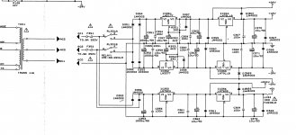
They were both full-wave rectified (the top schematic has an obvious blunder whereby the transformer is shorted out!)
Don't change the second circuit to half-wave, use another 25-0-25 secondary to power that,
it needs both diodes.
Thx alot for your answer. Appreciated it.
Maybe my blunder because i deleted some lines to show how i connected it. I will post orginal
Schematic again.
And a new one how its setup now
Attachments
why are you doing this? is there a particular reason for this mod?
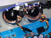
I wanted to split up the supply so audio section get its dedicated and both will run a bit cooler.
I think i will have audible benefit from this.
Last edited:
well if you get an audible benefit without increased noise that will be good, looking forward to the outcome.
can you explain how separating the sections allows them to run cooler?
2 PTs (50 and 30va) instead of estimated 20-30VA that orginal was.
Yes i will update how it will sound.
so your increasing available transformer current, correct?
still wondering how the sections will run cooler?
Yes more current correct. Well the PTs will run cooler but the regulators will be the same i guess. Will add some more heatsinking on all regulators also.
i'm not the best amp guy but doesn't changing the transformer not make the supply impedance different? and would that possibly effect stability? i sincerely hope your mod doesn't turn your amp into an oscillator....
I’m not sure either but hope not. What i know so far is that when i replaced the old pt to one one new toroid (the bigger 50VA) it didn’t sound worse or got more noisy, actually the opposite! With headphones and volume over half i don’t hear any noise.
But let’s see how that change using 2 pts..
So far so good.
It seems to work very well and current 0.09A amp and 12.6w (lower than before : 13.7w)
First turn on with lamp bulb tester and my smallest bulb (60w) it flashed a microsecond and then went dark.
Scope looks good although very limited (only max 5ghz)
I’ve listened quite much now and it’s for me a big difference, with half volume and in idle i don’t hear any hum or noise at all. A bit better than before.
When it comes to sound, well, i do really think it’s a major upgrade. Sound have become so ”open” and transparent. Fun to listen now")
It seems to work very well and current 0.09A amp and 12.6w (lower than before : 13.7w)
First turn on with lamp bulb tester and my smallest bulb (60w) it flashed a microsecond and then went dark.
Scope looks good although very limited (only max 5ghz)
I’ve listened quite much now and it’s for me a big difference, with half volume and in idle i don’t hear any hum or noise at all. A bit better than before.
When it comes to sound, well, i do really think it’s a major upgrade. Sound have become so ”open” and transparent. Fun to listen now
- Status
- This old topic is closed. If you want to reopen this topic, contact a moderator using the "Report Post" button.
- Home
- Amplifiers
- Power Supplies
- Adding a second transformer