I have a 120 V transformer that looks like it has dual center-tapped secondaries (image attached). Hoping someone can answer the following for me:
1) Can I parallel the secondaries and use this transformer as if it had a single center-tapped 24 V secondary winding?
2) If yes to 1), do I get 24 A, making this a ~576 VA transformer?
3) Anything I should know about the 3 V and 7 V windings?
Thanks in advance.
1) Can I parallel the secondaries and use this transformer as if it had a single center-tapped 24 V secondary winding?
2) If yes to 1), do I get 24 A, making this a ~576 VA transformer?
3) Anything I should know about the 3 V and 7 V windings?
Thanks in advance.
Attachments
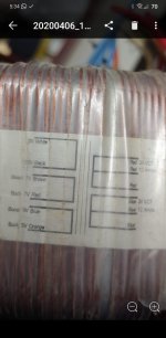
Probably, but given the dumb colour scheme you'll have to check the phasing yourself, and while you're at it you can check the voltages are an exact match (same number of turns in each secondary section).
The 3 and 7 volt windings are for tuning the primary - you put them in series with the primary to alter the transformer ratio slightly, and they can be in-phase or anti-phase to vary the ratio in either direction, which you can think of as allowing 110V, 113V, 117V, 120V, 123V 127V or 130V primary, or you can use them to adjust the output voltages up or down a little.
The 3 and 7 volt windings are for tuning the primary - you put them in series with the primary to alter the transformer ratio slightly, and they can be in-phase or anti-phase to vary the ratio in either direction, which you can think of as allowing 110V, 113V, 117V, 120V, 123V 127V or 130V primary, or you can use them to adjust the output voltages up or down a little.
Just to clarify for 3), I wasn't explicit on this point, they must not be used except with the primary, they are not properly isolated from the primary so connecting them to the secondaries is dangerous.1/ Yes
2/ Yes
3/ They are used to boost/cut other windings
Just to clarify for 3), I wasn't explicit on this point, they must not be used except with the primary, they are not properly isolated from the primary so connecting them to the secondaries is dangerous.
It doesnt show them connected to the primary.
The transformer is drawn in a confusing way.
It does say "boost" on those windings so you usually boost secondary windings.
i.e. where outputs are mosfets you have a higher voltage on the driver side.
Hi
I'm not a transformer expert but I do know that my own TX guy winds the primaries last. Since the two windings are labelled as 'boost' and 'buck', there is a strong suggestion that they are used only for the primary side. There may not be sufficient insulation between them and the primary to allow their use on the secondary.
Most agencies require that the total VA rating of the PT be printed on it.
It is safest to use the secondaries as separate supplies. For example, if you use this to power several audio channels, use two bridges and cap pairs for dual split rail supplies each supporting whatever number of audio PAs they can. Besides, it is easy to find 25A bridges for a few dollars where 50A bridges are tens of dollars.
What is the risk in paralleling the secondaries?Hi
I'm not a transformer expert but I do know that my own TX guy winds the primaries last. Since the two windings are labelled as 'boost' and 'buck', there is a strong suggestion that they are used only for the primary side. There may not be sufficient insulation between them and the primary to allow their use on the secondary.
Most agencies require that the total VA rating of the PT be printed on it.
It is safest to use the secondaries as separate supplies. For example, if you use this to power several audio channels, use two bridges and cap pairs for dual split rail supplies each supporting whatever number of audio PAs they can. Besides, it is easy to find 25A bridges for a few dollars where 50A bridges are tens of dollars.
Hi
I think the risk of paralleling windings is similar to paralleling DC supplies, where if there are DC resistance differences, the one supply will feed into the other, or the one winding may feed into the other. The result is that there may be heavier currents through the windings than what you are getting to the load.
The magnerising currents within transformers is astoundingly high.
Hi
I think the risk of paralleling windings is similar to paralleling DC supplies, where if there are DC resistance differences, the one supply will feed into the other, or the one winding may feed into the other. The result is that there may be heavier currents through the windings than what you are getting to the load.
The magnerising currents within transformers is astoundingly high.
I designed an SMPS with bi-filar secondary windings.
When I tested the SMPS it was drawing much more current on idle than it should. In the end it was the bifilar windings werent exactly the same length causing excess current draw from the primary.
Toroidals are primary first, at least I've only seen them this way - but the principle is the same, all the primary side windings are separated from all the secondary side windings with an extra insulation layer. Winding the primary first means you only need one such layer, not two (the magnetic core is inaccessible and doesn't need extra insulation from the primary).Hi
I'm not a transformer expert but I do know that my own TX guy winds the primaries last.
Secondary windings are thicker wire making the outside of the transformer much more robust too when wound this way.
Would it be possible to avoid this effect by only combining the outputs together after rectification? i.e. everything is "separated" until the capacitor bank? Or would the voltage differences between the secondary windings make it so that one secondary takes all the load?Hi
I think the risk of paralleling windings is similar to paralleling DC supplies, where if there are DC resistance differences, the one supply will feed into the other, or the one winding may feed into the other. The result is that there may be heavier currents through the windings than what you are getting to the load.
The magnerising currents within transformers is astoundingly high.
OK. I guess it's cheaper than buying a whole new transformer... I got this off eBay a long while back. It's a salvage from a large public sports display thingie.Using two rectifiers would help.
As one transformer is loaded its voltage will droop a bit causing other winding to start to give power.
Yes, exactly. Plus the fact that there's more time and labour involved. I'll do it if I think it's worth it, but want to avoid it if at all possible.If it is being used for a power amp application, why not have two separate rectifier/filters, one for each channel, it cost a bit more and takes up more space.
- Status
- This old topic is closed. If you want to reopen this topic, contact a moderator using the "Report Post" button.
- Home
- Amplifiers
- Power Supplies
- Toroidal transformer