I've got a hard time finding a clear answer to this rather simple question: how much mm should I leave between exposed pins carrying mains on a pcb and the edge of the board ?
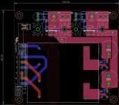
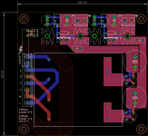
In the example attached, I've got 6.3mm between the edge of the board and the edge of the pads for the input terminal block. Is it enough ?
In the example attached, I've got 6.3mm between the edge of the board and the edge of the pads for the input terminal block. Is it enough ?
Attachments
6.3mm is plenty of distance with regard to normal spacing... and I would say it was OK under all conditions tbh including the possibility of a mains flashover if the board was right up against the edge of a chassis. That said, in that particular circumstance I would probably add some plastic shield for absolute piece of mind on the chassis case.
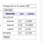
Remember 240 volt mains is 340 volt peak... so lets call it 400 and put that into an on-line calculator:
PCB Trace Spacing Calculation for Voltage Levels
Remember 240 volt mains is 340 volt peak... so lets call it 400 and put that into an on-line calculator:
PCB Trace Spacing Calculation for Voltage Levels
Attachments
6.3mm is plenty of distance with regard to normal spacing... and I would say it was OK under all conditions tbh including the possibility of a mains flashover if the board was right up against the edge of a chassis. That said, in that particular circumstance I would probably add some plastic shield for absolute piece of mind on the chassis case.
Remember 240 volt mains is 340 volt peak... so lets call it 400 and put that into an on-line calculator:
PCB Trace Spacing Calculation for Voltage Levels
That assumption is safe and sensible in the controlled World inside the device, after some power suppky, but not in the wild uncontroloed Mains World,
There is a reason for 1500V and 3000V HiPot tests being mandatory, and it´s such peak voltages being possible so often that they must be accounted for.
On this account, I would calculate safe distances based on these higher voltages.
If the edge of the pcb is against a metal chassis the clearance requirement will be different from it its in a plastic card guide rail.
I'd go with the ant test - if an ant can be electrocuted, the spacing is not generous enough - this is a possible failure mode, since a carbonizing/vaporizing ant/bug/spider can form an arc worst-case. Clearance distances also help protect against small metal foreign bodies rattling around causing dangerous situations (something that isn't unknown on the test bench!), and creepage is all about high humidity conditions where all surfaces are coated with a monolayer of water molecules and carry leakage current in strong fields. (This is why you don't get static electricity effects in damp conditions).
Mains carries occasional multi kilovolt spikes, due to inductive loads like old fluorescent lights and fridge motors and lightning surges, which is partly why the clearage and creepage distances are so large.
Thank you all for the answers.
The board is designed to fit into a 1U box. So the "left" edge wouldn't be against the chassis as I need to put a wall mounted fused/switched IEC there. The "bottom" edge otoh would go against the chassis. So I'll add 5mm of blank pcb there, to make certain enough distance is enforced. The keepout track visible on the picture is 10mm wide.
Btw, the transformer on this thing is 31.4mm high; With the pcb thickness, I'm at 33mm. In a 1U enclosure, that means 5mm standoffs and thus a plastic sheet under the pcb.
Attachments
Safety agencies UL, CSA, ETL all have an 8mm min from PRIMARY POWER to SECONDARY POWER. Double insulation,is keeping and primary wire from touching secondary parts. Other rules are also required, however this look like a DIY and not a product for sale. Use your own best rules. Always be on the safe side.
Duke
Duke
- Status
- This old topic is closed. If you want to reopen this topic, contact a moderator using the "Report Post" button.
- Home
- Amplifiers
- Power Supplies
- Safe distance between pcb edge and 230vac mains ?