Good day everybody,
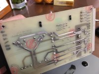
I had the power supply board with Schaffer transformer as image. But I couldn’t determine how to connect to 100v or 115 ac. Does anyone have schematic or experience with this?
Thank you very much in advance for your help.
I had the power supply board with Schaffer transformer as image. But I couldn’t determine how to connect to 100v or 115 ac. Does anyone have schematic or experience with this?
Thank you very much in advance for your help.
Attachments
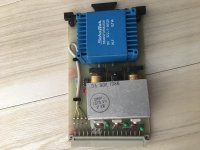
Assuming the transformer does in fact feature a split primary, the interesting part is not on your photos. Please take one from the underside, IEC / transformation region in particular. And preferably another from the top. You have skillfully missed basically everything primary side.
These or at least similar transformers are still being made. Split 115 V primaries seem to be a standard feature these days, but who knows about 1986.
https://www.weiss-trafo.de/fileadmi...er/Datenblatt_KLF-EN_Flachtransformatoren.pdf
These or at least similar transformers are still being made. Split 115 V primaries seem to be a standard feature these days, but who knows about 1986.
https://www.weiss-trafo.de/fileadmi...er/Datenblatt_KLF-EN_Flachtransformatoren.pdf
Thank you very much for your advises. Please kindly check the photos. I am happy if I could do something with it. Once again thank you
Attachments

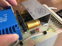
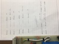
I can be sure that 4 lines are for input. Underside are pins for out only.
Simple measurement as photo. Assuming pri can be input with ac 115 and 230, I guess for my 100v system, I should do Brown&Green—White&Yellow for parallel input?
Please kindly correct me if I am wrong.
Simple measurement as photo. Assuming pri can be input with ac 115 and 230, I guess for my 100v system, I should do Brown&Green—White&Yellow for parallel input?
Please kindly correct me if I am wrong.
Attachments
If you are in the EU then it will be 230v primary voltage by default. Have you got 230v between Brown and yellow?
If you have then if you have half the voltage between Brown and Green, there is a good chance that connecting the Green to Yellow and Brown to White, it might work depending on the phasing of the windings.
Use an incandescent lamp in series with the supply in case of any issues. 40W is more than enough in wattage.
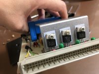
4 leads are brought to the connector. This means that 115V/230V selection is handled in the socket that this board plugs INto.
But since you don't show that, I'll work from the board, but you should trace-through to the backpanel socket and wire according to local voltage.
There are four wires for two windings. The connections look odd but actually minimize the re-jumpering to change 115 to 230. This is so widely used that I feel sure phasing has been taken into account.
> in Tokyo with 100vac from the wall.
Then you will be feeding 13% less than designed, and it may buzz bad. Are 100V:115V transformers a common thing there? There are other ways but I don't think you have the experience to do them *safely*.
Attachments
4 leads are brought to the connector. This means that 115V/230V selection is handled in the socket that this board plugs INto.
But since you don't show that, I'll work from the board, but you should trace-through to the backpanel socket and wire according to local voltage.
There are four wires for two windings. The connections look odd but actually minimize the re-jumpering to change 115 to 230. This is so widely used that I feel sure phasing has been taken into account.
> in Tokyo with 100vac from the wall.
Then you will be feeding 13% less than designed, and it may buzz bad. Are 100V:115V transformers a common thing there? There are other ways but I don't think you have the experience to do them *safely*.
Dear Sir,
Thank you very much for your advice.
I’ve tried to supply 100vac to Brown & White, measured vdc out, ok( 2x 12v & 05v according to the regulators. Not check for current yet). Then I tried with Green & Yellow, things were ok too. No buzz/hot.
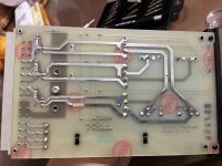
Basing on the cutting trace of the jumper between Green and White, I guess there used to be a jumper there for 230 input. In that case, can we determine phases of windings for a parallel input? Brown& Green—White&Yellow or vice versa, Brown&Yellow—Green&White?
I can find a 100 to 115 trans here. But if you don’t mind, could you please give a hint about other way? Don’t worry, it’s for reference purposes only.
")
Once again thank you for spending your previous time on my boring and stupid questions.
- Status
- This old topic is closed. If you want to reopen this topic, contact a moderator using the "Report Post" button.
- Home
- Amplifiers
- Power Supplies
- Schaffer transformer power connections