Hi, can anyone point me in the direction for a circuit diagram of a plus and minus 45volt regulated linear supply. Needed for the front end up to and including drivers of a class A amplifier, so only low current needed. Nothing too exotic or complicated. Thanks
Regards
Alan
Regards
Alan
I am so trivial and assume a symmetrical winding with mid-tap:
http://www.massmind.org/images/www/hobby_elec/gif/ckt21_1.gif
Replace D2 and D5 with power zeners in order to protect against dynamic over-voltages.
http://www.massmind.org/images/www/hobby_elec/gif/ckt21_1.gif
Replace D2 and D5 with power zeners in order to protect against dynamic over-voltages.
Then you can build two independant TL783 regulated supplies, and ground the positive end of one of them to create a negative supply.
The LM317HV Will also work in this application, The vanilla LM317 will see too much input-output differential voltage during startup and fault conditions to function properly.
Alternatively you can roll your own supply using discrete parts.
Edit 37VAC is a bit on the low end, if you take dropout voltage into account.
"The LM317HV Will also work in this application, The vanilla LM317 will see too much input-output differential voltage during startup and fault conditions to function properly." True, this is why I suggest to add a power zener (for each regulator) to protect the ordinary LM317 against too high voltage across input-output.
As you have two separate windings, you can use either a symmetrical regulator or two positive regulators that are stacked. Personally, I prefer a symmetrical regulator for noise reasons.
As you have two separate windings, you can use either a symmetrical regulator or two positive regulators that are stacked. Personally, I prefer a symmetrical regulator for noise reasons.
Fauxfrench, may be you missed the voltage level - 45 V. There isn't popular negative chips for that.
And second fact that positive regulators (317 etc.) usually have better specs. So, for noise reasons - two identical integral positive regulators have to be better.
I see two solutions: Either a set of LM317HV/LM337HV (the LM317HV can do 60V input-output and the LM337HV -50V input-output) OR ordinary LM317/337 with power zeners between input and output.
The power zeners I would make up of an ordinary zener (some 24V) and a darlington power transistor with the zener between base and collector and a 1K resistor between base and emitter to ensure full turn-off.
The LM317/337 have the advantage over 78XX/79XX that none of the pins are grounded. In principle, an LM317 can provide a 200V regulated output from a 220V input as long as the input-to-output voltage does at no moment exceed 37V (I am a "chicken" and have until now only tried with 42V input but no protection zener). It is the dynamic input-output voltage during start-up that is our concern. That is taken care of by the power zener circuit that reacts very fast and with large pulse current capacity if the input-output voltage momentarily exceeds some 26-27V.
Only in case of an output "hard-short-circuit" (zero output impedance instantly) with an active LM317 and fully charged power supply capacitors, the protection power zener circuit is challenged in full. How much current can the power supply capacitors provide as a surge when fully shorted? You hardly ever have a "hard-short-circuit" in an operating pre-amplifier circuit or a driver stage UNLESS you are about to make some tests and it is you creating the short-circuit. Do all testing with less than 37V input. If you are still worried, add a couple of Ohm between the power supply capacitors and the regulator for limitation of short circuit currents.
I know that many use stacked power supplies to generate symmetrical voltages and that positive regulators have slightly better specs than negative and are far more in choice. My reason to prefer symmetrical designs is that with stacked (positive) power supplies, both the ground rail and the negative rail have a direct connection to a noisy rectifier circuit (most often a bridge). My fear is that the gain in performance with only positive regulators is lost from having a negative rail with direct connection a the rectifier circuit.
Last edited:
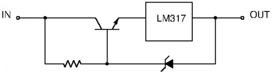
I forgot the modified HV version with dynamic drop transistor. That modification does not hamper current protection and there are no particular surge currents.
Though we do not have many negative voltage regulators, with simple means we can modify the LM317/337 to handle higher voltages at the input.
Though we do not have many negative voltage regulators, with simple means we can modify the LM317/337 to handle higher voltages at the input.
Attachments
What about adding an RC stage to isolate the negative supply leg of the negative regulator from the "Noisy" bridge rectifier? I still think the TL783 solution is more then adequate for the job at hand, if you need to feed very delicate circuits you can always add a RC filter down the line.
I have the schematics of a complex bipolar based supply somewhere, but that would need a completely new PCB design, that is relatively complex in comparison to two regulators.
I have the schematics of a complex bipolar based supply somewhere, but that would need a completely new PCB design, that is relatively complex in comparison to two regulators.
My fear is that the gain in performance with only positive regulators is lost from having a negative rail with direct connection a the rectifier circuit.
I don't think that is a concern. Remember, there is no 'noise' per se on any rail, also not on any negative rail. Noise is always between two nodes - when we talk about potential we really mean potential difference.
So when we use the negative rail as the reference for the negative supply, as we would do here, by definition that negative rail is absolutely noise free.
Jan
Thanks for the replies.
Transformer has two secondaries, 37-0. 37-0.
I require + and - forty five volts DC, say 300mA
Regards
Alan
What VA rating is the transformer? Do you want adjustable current limiting?
As a very practical approach, first build the rectifier/ filter cap part and measure the voltage you really get with your transformer. Should be around 55v at idle.
For a high quality power supply I would always start with a C-L-C filter. Combine the large electrolytics with some small film caps. It takes out a lot of ripple.
Then, a zener diode, darlington combination. it will only need two resistors and a capacitor to give a very stable output, even better than a simple regulator. So you have 5-6 parts that form your regulator circuit. You can add a pot to fine tune. Last, put a diode over emitter/ collector, to prevent voltage from reversing. This is a very uncritical, simple discrete regulator with high quality.
Only down side, it is not short cut protected. With a 200 VA transformer, not the best to experiment with. You can over dimension the darlington (cheap) and put a resistor between the unregulated and regulated side, to limit current for a short time protection. Not elegant, but simple and effective.
If you use 300mA, you have to be sure the power transistor can vent about 8
W of heat away.
Those values have to be adjusted to your voltages and you repeat the circuit for the negative side with the complementary PNP transistor. If you do not feel comfortable with that, ask.
maybe have a look here: Transistor-Zener Diode Regulator Circuits
and : Filter circuits - Inductor Filter, LC filter, CLC or PI filter, Capacitor filter | D&E notes
Attachments
Last edited:
- Status
- This old topic is closed. If you want to reopen this topic, contact a moderator using the "Report Post" button.
- Home
- Amplifiers
- Power Supplies
- Regulated linear supply