Hi thank you for the reply. Well 40 uf is from 10uf parallel caps that I've got & the 39uf which I goofed is supposed to be 49uf Obligatto caps that I have as well.
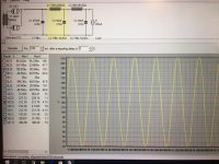
May I ask what software are you using ? After I posted this thread I tried 100uf at C2 which produce much better results but I trying to learn how to decipher the readings.
May I ask what software are you using ? After I posted this thread I tried 100uf at C2 which produce much better results but I trying to learn how to decipher the readings.
I don't know the software,Psud2, myself or the particular application it might be used with. I assume, the give away would be the valve rectifiers, high voltage/low current and brick sized inductors, that it is used to design filters for valve power supplies. I would hazard a guess that it comes with some form of user manual. Perhaps you should read that rather than arbitrarily throw components in a simulation.
Better advice might be to ignore me given I know little to nothing about valve gear or the filters that might or should be used with them. It's a power supply so normal rules do not necessarily apply. All I would care about is the surge rating of the input diode valve, it's repetitive peak and average ratings and then, to be honest, slap some values in LTSpice.
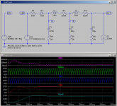
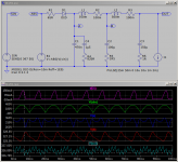
No real rhyme or reason to the attached.
Better advice might be to ignore me given I know little to nothing about valve gear or the filters that might or should be used with them. It's a power supply so normal rules do not necessarily apply. All I would care about is the surge rating of the input diode valve, it's repetitive peak and average ratings and then, to be honest, slap some values in LTSpice.
No real rhyme or reason to the attached.
Attachments
I mean... Like. Your simulation circuit has an AZ1 valve in it. Does your actual circuit have an AZ1 valve in it. Psud2 probably simulates based on an AZ1 valve.
AZ1 @ The Valve Museum
http://www.r-type.org/pdfs/az1.pdf
16uF 60mA Plate Resistance[?] 3K
As I say I know nothing but without you knowing more about what you are trying to achieve with what you have then you will be going nowhere.
AZ1 @ The Valve Museum
http://www.r-type.org/pdfs/az1.pdf
16uF 60mA Plate Resistance[?] 3K
As I say I know nothing but without you knowing more about what you are trying to achieve with what you have then you will be going nowhere.
sumotan, it would help a lot if you provide all the details you know of the parts you have or are aiming to use - including the power transformer and the load circuit - and what you are aiming to get from the simulation (compared to building the power supply and taking whatever measurements are of interest to you).
Simulation is only as good as the closeness of the modelled parts to the parts you have; your appreciation of what can't be modelled accurately; and what you are aiming to 'see' with a simulation result
Simulation is only as good as the closeness of the modelled parts to the parts you have; your appreciation of what can't be modelled accurately; and what you are aiming to 'see' with a simulation result
Hi Guys,
Thanks for the advice. Yes the simulations excluding the 10H Hammond choke is base on parts that I have. This PS simu is to power Ale's 01A preamp with mosfet source follower.
Transfomer is custom wound split bobbin unit. Purpose is to get as clean a supply & learning how to read & understand what the simu shows in details
Thanks again
...advice if the result is good or ?...
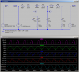
Good for what? How good does it have to be? It's all relative. A door-bell hardly cares. A power stage can often stand 5% ripple. A phono preamp has to be really clean.
PSUD is easily-found freeware. No manual; it "assumes" you could design a supply by hand, but want help with computations. It is NOT vacuum-tube specific.
The choice of rectifier valve hardly matters with a mere 25mA load. Changing rectifiers on this plan only changes the output about 1%.
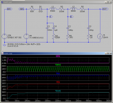
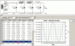
Here's an alternate plan, one more low-cost part, which gives 16 microVolts ripple. That will be good for almost any tube preamp.
Attachments
- Status
- This old topic is closed. If you want to reopen this topic, contact a moderator using the "Report Post" button.
- Home
- Amplifiers
- Power Supplies
- Psud2 simu advice