I am putting together a simple regulated 3 amp variable voltage power supply, and I am planning on using 3 LM317T's on a shared heatsink.
Is there any traps I need to know or will wiring three in parallel be fine? When the LM317T is heatsinked, it is rated for 1.5 amps, so I figure 3 should be overrated sufficiently for 3 amps, but I am unsure if I should be careful how I wire them in parallel, to avoid thermal runaway or current imbalance.
Is there any traps I need to know or will wiring three in parallel be fine? When the LM317T is heatsinked, it is rated for 1.5 amps, so I figure 3 should be overrated sufficiently for 3 amps, but I am unsure if I should be careful how I wire them in parallel, to avoid thermal runaway or current imbalance.
Last edited:
That doesn't sound like a great idea tbh and you could end up with stability issues and more basic issues of the regulators 'fighting' each other due to differences in voltage tolerances.
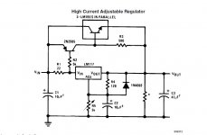
The data sheet shows the recommended method of adding an external series pass device, however the device used is an odd ball:
http://www.ti.com/lit/ds/symlink/lm395.pdf
There are probably more modern solutions than this... but paralleling three LM317's to make a variable supply would be a no no in my book.
Attachments
That's what I was worried about. Yeah, a power transistor supplying the actual current sounds like a good idea.That doesn't sound like a great idea tbh and you could end up with stability issues and more basic issues of the regulators 'fighting' each other
I did find this just now, though:
Power supply 4.5 A with 3 LM317 in parallel - Power Supply Circuits
The english isn't very good, but it does seem to warn about potential problems if you over drive the power supply.
Last edited:
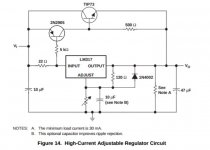
3 voltage regulators parallel is a dumb idea in general. Parallel the pass transistors, not the voltage source. Follow the pass transistors with emitter resistors, about 0.22 ohms or so, to share the current.
I used a dumb 1.5 W zener diode (protected by current limit resistors to limit wattage) feeding bases of 5 TIP142 darlingtons to make a 6.5 A voltage regulator. Heat sink was off of a generation 3 PC CPU. Runs daily about 14 hours in my ST120 hifi amp. About a 2 v loss from the nominal zener voltage to the actual output voltage. Eliminates the 2n2905 and the two resistors in post #3. TIP142 are very cost effective, about $1 for 1.2 amp safe current.
I used a dumb 1.5 W zener diode (protected by current limit resistors to limit wattage) feeding bases of 5 TIP142 darlingtons to make a 6.5 A voltage regulator. Heat sink was off of a generation 3 PC CPU. Runs daily about 14 hours in my ST120 hifi amp. About a 2 v loss from the nominal zener voltage to the actual output voltage. Eliminates the 2n2905 and the two resistors in post #3. TIP142 are very cost effective, about $1 for 1.2 amp safe current.
Last edited:
Yes, plenty of 3-5A options in the same package as an LM317 -> much easier to work with.
Yup. Why not try LM350? Same form factor. Just make sure to match rectifier diode amperage to 3A or a bit higher.
I recall an Elektor design of some decades ago where they put five LM317's in parallel. They had current balancing resistors in their output lines, and either voltage control and current limitation were outsourced to a pair of opamps. Hence the LM's were degradated to plain pass elements  .
.
Best regards!
.Best regards!
- Status
- This old topic is closed. If you want to reopen this topic, contact a moderator using the "Report Post" button.
- Home
- Amplifiers
- Power Supplies
- Question regarding the LM317T