Hi all, I am planning to build a lm3886t based amplifier and I prefer Class II electrical wiring, even though many recommends Class I. This is because Class II seems easier to me. To achieve high safety level, I plan to make the following steps:
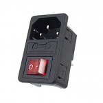
1. Solder C8 main socket live and neutral pin to primary winding connecting wires of my toroidal transformer.
2. Extra heat shrink tubing around the primary winding wires of the transformer (The wire had double insulated PVC already, so adding this would make it triple insulated).
3. Apply silicone sealants to the soldered pin of the main socket to make sure there is no open electrical path along the mains current carrying wires.
The transformer is a nuvotem talema 225va open toroidal transformer and I will be using a plastic enclosure for my amp. Does these steps sufficient to maintain the electrical safety level? Thanks.
You seem to be missing a fuse also. That will need the same treatment as your mains input socket.
I assume you will solder the mains connections and heatshrink them before any silicone? This will provide mechanical support. Don't use normal silicone to seal electrical connections as it will corrode them, you need special electronic silicone.
I assume you will solder the mains connections and heatshrink them before any silicone? This will provide mechanical support. Don't use normal silicone to seal electrical connections as it will corrode them, you need special electronic silicone.
Last edited:
Most important is that the transformer is class II, it should have the double insolation symbol on it.

Just to clarify any differences in legislation and safety;
Understandably, confusion often exists regarding the difference between Class 2 and Class II rated ac-dc power supplies. The differences are significant and important to understand.
The NEC (National Electric Code) identification of Class 2 refers to the output voltage and power capabilities of ac-dc supplies, while the IEC (International Electrotechnical Commission) designator of protection, Class II, refers to a power supply’s internal construction and electrical insulation.
The IEC protection classes govern the construction and insulation of power supplies to protect the user from electrical shock. In a Class II power supply, there are two layers of insulation (or a single layer of reinforced insulation) between the user and the internal current carrying conductors. In supplies designed with two layers of insulation, the first layer of insulation is typically referred to as “Basic Insulation.” A common example of basic insulation is the insulation present on wires. The second layer of insulation is often an insulating case enclosing the product.
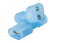
The most important thing that people overlook is the mains input connector wiring. The conductors on the socket must be crimped to avoid wiring unsoldering itself and shorting to ground. There is no earth wire in Class II.
A transformer does not have the Class II symbol, it is not a finished product.
Class II

Class II symbol
A Class II or double insulated electrical appliance is one which has been designed in such a way that it does not require a safety connection to electrical earth (ground).
The basic requirement is that no single failure can result in dangerous voltage becoming exposed so that it might cause an electric shock and that this is achieved without relying on an earthed metal casing. This is usually achieved at least in part by having at least two layers of insulating material between live parts and the user, or by using reinforced insulation.
In Europe, a double insulated appliance must be labelled Class II or double insulated or bear the double insulation symbol: ⧈ (a square inside another square).
Insulated AC/DC power supplies (such as cell-phone chargers) are typically designated as Class II, meaning that the DC output wires are isolated from the AC input. The designation "Class II" should not be confused with the designation "Class 2", as the latter is unrelated to insulation (it originates from standard UL 1310, setting limits on maximum output voltage/current/power).
Understandably, confusion often exists regarding the difference between Class 2 and Class II rated ac-dc power supplies. The differences are significant and important to understand.
The NEC (National Electric Code) identification of Class 2 refers to the output voltage and power capabilities of ac-dc supplies, while the IEC (International Electrotechnical Commission) designator of protection, Class II, refers to a power supply’s internal construction and electrical insulation.
The IEC protection classes govern the construction and insulation of power supplies to protect the user from electrical shock. In a Class II power supply, there are two layers of insulation (or a single layer of reinforced insulation) between the user and the internal current carrying conductors. In supplies designed with two layers of insulation, the first layer of insulation is typically referred to as “Basic Insulation.” A common example of basic insulation is the insulation present on wires. The second layer of insulation is often an insulating case enclosing the product.
The most important thing that people overlook is the mains input connector wiring. The conductors on the socket must be crimped to avoid wiring unsoldering itself and shorting to ground. There is no earth wire in Class II.
A transformer does not have the Class II symbol, it is not a finished product.
Class II

Class II symbol
A Class II or double insulated electrical appliance is one which has been designed in such a way that it does not require a safety connection to electrical earth (ground).
The basic requirement is that no single failure can result in dangerous voltage becoming exposed so that it might cause an electric shock and that this is achieved without relying on an earthed metal casing. This is usually achieved at least in part by having at least two layers of insulating material between live parts and the user, or by using reinforced insulation.
In Europe, a double insulated appliance must be labelled Class II or double insulated or bear the double insulation symbol: ⧈ (a square inside another square).
Insulated AC/DC power supplies (such as cell-phone chargers) are typically designated as Class II, meaning that the DC output wires are isolated from the AC input. The designation "Class II" should not be confused with the designation "Class 2", as the latter is unrelated to insulation (it originates from standard UL 1310, setting limits on maximum output voltage/current/power).
Thank you guys for the response.
My transformer has the sign 'Class II to EN61558'.Most important is that the transformer is class II, it should have the double insolation symbol on it.
Yes I will include a main fuse at the live pin. I will solder and then apply silicone. I am thinking of using neutral cure silicone instead. Is there any risk of using normal silicone?You seem to be missing a fuse also. That will need the same treatment as your mains input socket.
I assume you will solder the mains connections and heatshrink them before any silicone? This will provide mechanical support. Don't use normal silicone to seal electrical connections as it will corrode them, you need special electronic silicone.
Yup certainly I will make sure the soldering be intact. The heatshrink tube will cover as much the solder joint as possible,e.g. hitting the main socket plastic part, before applying silicone. So the silicone will wrap around the heatshrink tubing, which cover the solder joint between wire and socket pin.Make sure all cables are well fixed in place, both insulated bits and when passing through solder terminals (wrap them around securely). If a mains solder joint did melt due to a fault you don't want a mains wire coming loose in the box (plastic or metal).
A plastic box, a IEC mains inlet with mains switch and fuse holder incorporated and insulated female spade connectors to the transformer's primary. Just arrange things physically with the primary wires short enough so that even if they get lose, they won't reach the rest of the circuit and give you a shock through I/O ports. Fuses at the secondary side, before and after the rectifiers, provide an extra safety level.
Attachments
Don't forget, Class II is where there is no chance of continuity/leakage from the primary mains side to the output. Nothing to do with fuses, but good to include a primary fuse and if the correct value is selected, that is all that is needed to protect the secondary from over current.
If you build something for yourself, regulations are a good base, but don't try to follow them to the letter, like the manufacturers do: they try to comply AND spend a minimal amount of money.
Your main concern should be your safety, and common sense and a good understanding of problems are your best friends.
If in doubt, add a supplementary layer of insulation, and/or ask more experimented people on this forum.
If you try to follow too closely the rules, you run the risk of missing some important safety details.
For a home builder, one additional £, $ or € spent on a project is negligible, and it can make a lot of difference safety-wise, so never hesitate.
Really bad. What happens if someone uses a different cable?
How high is the maximum current? Is a C7 cable and connector the right choice?
The connector and cable are right, a C7 cable and a C8 socket. I will include a main fuse then.
Are you concerned with ground loops through the mains earth?Hi all, I am planning to build a lm3886t based amplifier and I prefer Class II electrical wiring, even though many recommends Class I. This is because Class II seems easier to me.
There may be another way to resolve potential problems and retain protective earth
The objective is to completely cover any live conductive part with best insulation. Maybe a coating of adhesive/sealant between the heatshrink and the iec socket?I don't really think adding silicone or araldite is going to achieve anything. You would probably be better off just adding another layer of heatshrink over the joint.
I mainly uses portable player like smartphone or ipod as the input source for my amplifier so ground loop is not a concern here. The reason I prefer class II is that I am confident in applying perfect insulation to completely seal the hazardous live conductive path which make designing a safe PE connected circuit a bit redundant.Are you concerned with ground loops through the mains earth?
There may be another way to resolve potential problems and retain protective earth
- Status
- This old topic is closed. If you want to reopen this topic, contact a moderator using the "Report Post" button.
- Home
- Amplifiers
- Power Supplies
- Class II power supply wiring