Been Playing around with a 6.8/6.9 V referenced Regulator and thinking about the LM329 but have a zener in there for ease. My Aim was shooting for the lowest and most even impedance possible. Sziklai's and CCS feeds were the winner after basic darlingtons. Just curious if there are any glaring problems I may have missed. I am learning LTSPiCe thanks to Mooly. I'm getting as low as 200 uOhms until I add rectifier input. The noise figures seem decent -105 dB @10Hz sloping down to -170 dB at 25K
Could this approach the performance of a "super-reg"? My thoughts are why use an opamp with all those tiny transistors when you can use 5 discrete transistors and not need a 15V rail.
BTW these are to be 100-200 mA max for Tube Preamp stages. Also R7 would be a 2K pot to dial in the output.
Could this approach the performance of a "super-reg"? My thoughts are why use an opamp with all those tiny transistors when you can use 5 discrete transistors and not need a 15V rail.
BTW these are to be 100-200 mA max for Tube Preamp stages. Also R7 would be a 2K pot to dial in the output.
Attachments
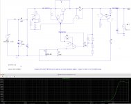
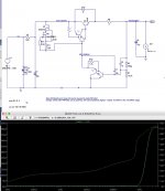
Here's a bit on the progression from basic NPN error and TIP50 pass BJT.
Most of the taming of impedance was due to the CCS sections. Without CCS or error amp the impedance was around 300 Ohms according to sims.
Higher LF Impedance and fairly flat from 60-100 Millohms

the Darlington on pass makes z average 1.5 mill ohm with a peak of 160 mOhm at 2.5 MHz
This shows both sections with compounded BJT's approaching 100 uOhm Z

Most of the taming of impedance was due to the CCS sections. Without CCS or error amp the impedance was around 300 Ohms according to sims.
Higher LF Impedance and fairly flat from 60-100 Millohms
the Darlington on pass makes z average 1.5 mill ohm with a peak of 160 mOhm at 2.5 MHz
An externally hosted image should be here but it was not working when we last tested it.
This shows both sections with compounded BJT's approaching 100 uOhm Z
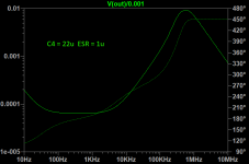
When you simulate, strip it down first -- i.e. take out the protection circuitry.
A peaking of the output impedance indicates stability issues. (let the Y-axis auto-scale). Try using a larger cap with some ESR on the output.
The gain of the pass transistor and speed of the error amplifier circuitry dominate the impedance.
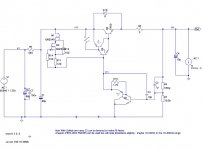
I am always interested in HV regulators, can't quite make out the component values however.
A peaking of the output impedance indicates stability issues. (let the Y-axis auto-scale). Try using a larger cap with some ESR on the output.
The gain of the pass transistor and speed of the error amplifier circuitry dominate the impedance.
I am always interested in HV regulators, can't quite make out the component values however.
Thanks Jack. For now I redid the screenshot. BJT's are ZTX458 and ZTX758. Most of the values are just fine tuning for voltage and low Z. Do you think a peak from 200uOhms to 180mOhms at 2 MHZ would be a problem for a tube supply though? mu thought were that if were flat from 10-100k it would be acceptable.
300V larger
300V larger
You can look at "Q" of the output impedance to ascertain stability. (Hint, use 1mA or 25mA perturbation current). In fact, it's easier to use output impedance than it is to break the feedback loop and deal with phase and gain separately.
Phase margin is related to Q by the following approximation:
Phase Margin ~= 50.36 * Q^(-0.907)
(See Sandler, "New Technique for Non-Invasive Testing of Regulator Stability", https://www.powerelectronics.com/power-electronics-systems/new-technique-non-invasive-testing-regulator-stability")
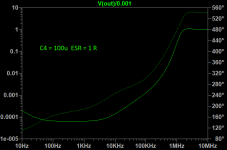
C4 figures importantly, using 100uF with a 1R snubber works well:
Phase margin is related to Q by the following approximation:
Phase Margin ~= 50.36 * Q^(-0.907)
(See Sandler, "New Technique for Non-Invasive Testing of Regulator Stability", https://www.powerelectronics.com/power-electronics-systems/new-technique-non-invasive-testing-regulator-stability")
C4 figures importantly, using 100uF with a 1R snubber works well:
Attachments
Yeah I read, maybe here, that C4 position caps with zobel/snubber resistor was a fad that designers were putting them there bc people,expected them. So I didn’t put it in. But I guess you may as well have tuning capability. I guess some like zobel some don’t. I know they make a difference in transformers and speakers.
I’ve never hear the term perturbation current before. I guess I need to hit the books a bit. I’m still getting over the LTSPICE learning curve so... i’m Not 100% on my testing methods.
I’ve never hear the term perturbation current before. I guess I need to hit the books a bit. I’m still getting over the LTSPICE learning curve so... i’m Not 100% on my testing methods.
Last edited:
Yeah I read, maybe here, that C4 position caps with zobel/snubber resistor was a fad that designers were putting them there bc people,expected them. So I didn’t put it in. But I guess you may as well have tuning capability. I guess some like zobel some don’t. I know they make a difference in transformers and speakers.
I’ve never hear the term perturbation current before. I guess I need to hit the books a bit. I’m still getting over the LTSPICE learning curve so... i’m Not 100% on my testing methods.
Not “tuning” its stability. Without the correct ESR you design will oscillate somewhere between 350 and 600 kHz, oscillation leads to smoke.
Question: why do you need that 6.8V offset on the bottom of the error darlington? Why not just ground it? Takes care of several concerns.
Jan
Something Like this Jan?
Attachments
Question: why do you need that 6.8V offset on the bottom of the error darlington?
Why not just ground it?
That's the reference voltage for the regulator. It's the input, amplified by the nfb network,
giving the regulated output voltage. Same equation as a non-inverting amplifier, with 6.8V input.
Vout = 6.8V x ( 1 + 420k/10.62k ) = 276V
Last edited:
That's the reference voltage for the regulator. It's the input, amplified by the nfb network,
to give the regulated output voltage.
Vout = 6.8V x ( 1 + 420k/10.62k ) = 269V
Thanks for the formula Ryama! I loves my spreadsheets of EE formulas. My question is that in Merlin’s PS book he talks about the reference voltage being 1/3 of the supply. Is using a small reference that bad? Some HV super regs use the 6.8 or 6.9 ref.
Merlin’s PS book he talks about the reference voltage being 1/3 of the supply.
Is using a small reference that bad? Some HV super regs use the 6.8 or 6.9 ref.
It's like setting the gain of an op amp. Smaller reference (input voltage) means a
higher regulator gain is needed. The most stable voltage references are around 6V-7V.
You could stack several of these voltage references to go higher for Vref if necessary.
Low regulator gain may have regulator stability issues, though.
Last edited:
That's the reference voltage for the regulator. It's the input, amplified by the nfb network,
giving the regulated output voltage. Same equation as a non-inverting amplifier, with 6.8V input.
Vout = 6.8V x ( 1 + 420k/10.62k ) = 276V
Of course, I (and most here) know that. The question is, why do you need it here? It is superfluous, because the error amp is single ended.
Jan
Last edited:
Smaller reference (input voltage) means a
higher regulator gain is needed.
Actually, with the cap bypass, the gain is always one, independent of the resistor ratio. So for that, any offset at the emitter doesn't make any difference.
Jan
Thanks for the formula Ryama! I loves my spreadsheets of EE formulas. My question is that in Merlin’s PS book he talks about the reference voltage being 1/3 of the supply. Is using a small reference that bad? Some HV super regs use the 6.8 or 6.9 ref.
Here's a simplified version of the circuit that makes the operation more clear.
A bypass capacitor is often added from output to wiper (regulator inverting input)
to lower the hf Zout, but that does not change the DC gain (regulated DC voltage).
Lecture 28
Attachments
Last edited:
while we're on math ( I keep on relearning 8th grade stuff) To get R2 is it this?
From Vout = Vref(1 + R2/R1)
(Vref X R1)/Vout = R2
Below images are per Jan's question. I think it's fairly comparable but we may be sacrificing noise for low Z. I think most of the low Z success is the compound amps and CCS.
Edit:
Actually the resistive ref has a Z of below 150u from 100Hz to 20KHz whereas the LM329 ref was slightly higher around 205uOhms
Attachments
Last edited:
while we're on math ( I keep on relearning 8th grade stuff) To get R2 is it this?
Vout = Vref x ( 1 + R2/R1)
Divide both sides by Vref:
Vout/Vref = (1 + R2/R1)
Subtract 1 from both sides:
Vout/Vref -1 = R2/R1
Multiply both sides by R1:
R1 x (Vout/Vref -1) = R2
Notice that Vout must be larger than Vref, or R2 is not realizable (positive).
Last edited:
Thanks for the Math lesson(not sarcastic) I found this handy sites row those who can't remember how to do squat.
solve for x, x/a +b=c - Solve For a Variable Calculator - Symbolab
I transposed the R and actually wanted the bottom value which I finally found to be
R2 = Vref x R1 / (Vout - Vref)
if Vout = Vref x ( 1 + R1/R2)
Does the .6 V from the transistor come into play because my calculations were screwy?
solve for x, x/a +b=c - Solve For a Variable Calculator - Symbolab
I transposed the R and actually wanted the bottom value which I finally found to be
R2 = Vref x R1 / (Vout - Vref)
if Vout = Vref x ( 1 + R1/R2)
Does the .6 V from the transistor come into play because my calculations were screwy?
- Status
- This old topic is closed. If you want to reopen this topic, contact a moderator using the "Report Post" button.
- Home
- Amplifiers
- Power Supplies
- Low Z HT regulated Power Supply w Sziklai