


I have not seen this kind of implementation before. Can you explain a few points about it:
How is the "active" control of the adjust pin voltage an improvement over a circuit using the LM317/337 that includes a capacitor (e.g. 10uF) between the adjust pin and ground (See datasheet for example)? That is often used to keep noise low. How much lower is the active approach, or is further reducing the noise not the primary goal of your circuit?
What is the intended purpose and applications for the "remote sense" connections? Would that not be another source of noise on the ADJ pin even though the load to ground in the circuit is only 33R? Also, Vout is set to 24V as you have shown the remote sense feedback path will be drawing almost 0.75A by itself. That's a good portion of the max rated current for the devices even when heatsinked (about 3A max). Can you explain this choice in a bit more detail?
The impedance driving the ADJ pin of the LM317 regulator IC is approx (R14 parallel R13) = 20 ohms.
To get an impedance of 20 ohms or less, at the ripple frequency (120 Hz), using only a capacitor on the ADJ pin, you'd need that capacitor to be 66 microfarads or greater. (math: 1/(2*pi*120Hz*66uF) = 20). And you'd also need a safe-discharge-current-path diode to protect it. D15 on the schematic.
To get an impedance of 20 ohms or less, at the ripple frequency (120 Hz), using only a capacitor on the ADJ pin, you'd need that capacitor to be 66 microfarads or greater. (math: 1/(2*pi*120Hz*66uF) = 20). And you'd also need a safe-discharge-current-path diode to protect it. D15 on the schematic.
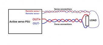
AC Error Correction is used OPAMP to make lower noise and using remote sense to get very stable output voltage...connection for remote sense is as follows...the improved output PSSR depends on used OPAMP, and if you use like on schematic you will get -120dB output PSRR.
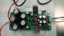
I only design PCB using help of Dragan100 from other forum, and he designed this very nice shematic and help me designing PCB.
You can build this one using above files at home (PCB eatching) and see how this is very nice and usefull circuit.
Attachments
Last edited:
AC Error Correction is used OPAMP to make lower noise and using remote sense to get very stable output voltage...connection for remote sense is as follows...the improved output PSSR depends on used OPAMP, and if you use like on schematic you will get -120dB output PSRR.
I only design PCB using help of Dragan100 from other forum, and he designed this very nice shematic and help me designing PCB.
You can build this one using above files at home (PCB eatching) and see how this is very nice and usefull circuit.
Yes, thanks, I already understood how the remote sense is to be connected.
My question was more about what potential audio application you had in mind for the remote sensing? Some class-A line level amplification perhaps?
In mind was all stuff to be powered from +/-15VDC to +/-24VDC with current max 200mA, so it can be preamplifier, buffer, DAC, equilizer, tone control etc.
It is in class like shunt PSU but with lover dissipation, and ether shunt PSU is parallel device this Active Servo PSU is serial device.
Do you plan to build it? You will be positive suprised how it make improvement to your preamplifier.
It is in class like shunt PSU but with lover dissipation, and ether shunt PSU is parallel device this Active Servo PSU is serial device.
Do you plan to build it? You will be positive suprised how it make improvement to your preamplifier.
- Status
- This old topic is closed. If you want to reopen this topic, contact a moderator using the "Report Post" button.