Hi,
After running fine for weeks, the power supply in my tube dac failed quite spectacularly today, right after turn on. Lots of black smoke and a burned pcb.
From the looks of it, R11 and C10 across the power transformer secondaries are the cause, they are both completely turned to coal and caused the pcb to burn.
I build it as a kit and am not quite sure what their function is in the circuit. Can anybody tell me / guess what likely happened (bad rectifier? short somewhere?)
Also, any safety measures I can install/add to make the device shut off when something like this happens? Shouldn't this have blown the fuse?
Thanks
Attachments
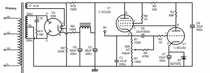
15k ? It seems very high for a snubber network and suggests around 17ma current flow and over 4 watts dissipation.
That cap needs to be rated way over 600 volt AC working (imo) for safe and reliable operation and that severely limits your choice.
Could you not snubber each winding separately?
That cap needs to be rated way over 600 volt AC working (imo) for safe and reliable operation and that severely limits your choice.
Could you not snubber each winding separately?
Sorry, yes, 4700pF
Typo in the manual
But anyway, I understand it better now, thank you all. I'm going to rebuild it without the snubber first, see if it makes any difference.
One question remains, why did the components fail after dozens of hours of running. Switch-on spike, just bad luck, something else? It scared me a bit because if I wasn't sitting next to it when it happened, it could easily have caught fire
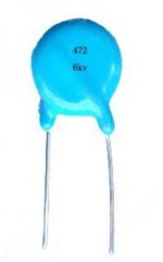
That application could also benefit from using an X rated cap, to provide a more benign failure process.
But as identified, the snubber should be two separate snubbers across each 330-0 secondary half-winding, as that is what is being snubbed, and will require a cap with a lower voltage rating.
If you are really keen to include such snubbers then I recommend checking out the quasimodo related threads here as to the most appropriate manner to size such snubbers.
A secondary fuse in the CT line is well worth considering, but of more benefit imho is to insert a 1N4007 in series with each 6X5 anode, to avoid future damage when the 6X5 fails.
Hopefully the HT adjust pot is good quality, as there is no fail-safe resistor if the wiper goes bad.
Last edited:
You don't need that. IMHO you don't want it. Break-off the coal (preferably snip leads) and carry on.
Haha yes! Maybe check remove the 6x, check for the 6.3 V and parts near it for correct values, like the choke etc...
Might want to use a variac to power up if the 6x is going to break down.
> 6x is going to break down.
"6X"? 6X5? That's unlikely to have caused this failure. Almost certainly the cap went short. The resistor gets 20+ Watts and becomes over-cooked. As others have said, if this is supposed to reduce incoming crap, it might possibly be better as two RC networks to ground. But millions of tube-toys have worked fine without such fancy-stuff.
The cap is high-stress, yet the part reported "might" be ample, yet it failed. Such applications are sometimes tougher than they look. If it were essential, there are caps which are made to fail open rather than short. But I stick with my opinion: he does not need this.

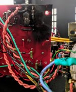
I agree. I've seen many boards burn up like that (CRT TV's) and depending on the damage the carbonised area could be cut out and filled with epoxy putty or components supported more freely.
Many such cases used to have the chassis written off on safety grounds as carbonised PCB is conductive and becomes a fire/safety hazard.
Many such cases used to have the chassis written off on safety grounds as carbonised PCB is conductive and becomes a fire/safety hazard.

- Status
- This old topic is closed. If you want to reopen this topic, contact a moderator using the "Report Post" button.
- Home
- Amplifiers
- Power Supplies
- Diagnose ps failure