Troubles with Texas Instruments LM337LZ [solved]
I just built a bipolar power supply based on Doug Self's Small Signal Audio Design book.
The positive supply is regulated by an ON Semi LM317LZ, and the associated output voltage is dead on.
The negative supply is regulated by a Texas Instruments LM337LZ, but the output voltage is only about 72% of what it should be. Looking at the controlling node, which should be a nominal 1.25 V, I'm measuring only 0.9 V! I thought this particular 337 might have been damaged by connecting a transformer with too much AC voltage, so I replaced it with a new LM337LZ and used a smaller AC voltage. Same results. I then thought that it might be the protection diode across that node, so I removed the diode. Still 0.9 V!
What could possibly cause this?
Looking at the data sheet, the reference voltage should fall between 1.20 V and 1.30 V, never as little as 0.9 V.
I noticed that the ON Semi and TI data sheets suggest (require?) a 240 Ω or 249 Ω resistor across the voltage reference. Doug has a 100 Ω resistor in this position. The voltage calculation formula is still the same, but I wonder whether the 100 Ω resistor that I'm using is somehow not presenting enough of a load.
I'm testing the power supply with no load at the moment. That doesn't seem to be a problem for the positive supply. Maybe I need to connect the 100 µF caps to the outputs?
Another detail is that I'm using a two-pin AC wall wart rather than a raw transformer. Since this doesn't provide a center tap, I'm using a capacitor voltage doubler to separately feed the positive and negative regulators. Unfortunately, the 16 VAC adaptor that I started with produces too much voltage : around 40 V. That's right at the limit of the regulators. So, after replacing the LM337, I have only connected a 12 VAC adaptor that produces only about 28 V at the regulator inputs. That should be safe. I'm planning to buy a 9 VAC adaptor since I really only need about 20 V to feed my +/-17V supply.
I can attach a schematic, if that would help. I'm pairing 1.3 kΩ resistors with the 100 Ω resistors to adjust each regulator to 17.5 V.
Last edited:
That was it!Negative integral regulators usually are more skittish-notional-capricious. They need that everything was as in the dataseet - they need all bypass caps, load not less than and so on.
100 Ohm is ok.
I finally got around to connecting the output cap. My power supply board plugs in to the audio board, and I thought it made more sense to put the output caps "local" to the audio board where they connect directly to the power planes. Unfortunately, this means that when I tested the power supply PCB by itself, the regulators had no load capacitance at all. I should have known better, since the data sheet basically requires a 1 µF output capacitor.
The positive regulator may not have had a problem with this (no) load, but as you said the capricious negative regulator was very unhappy.
Thanks!
Be carefull with the output capacitor!
If you look at the datasheet a solid tantalum or electrolytic is recommended.
I once had an unstable regulator using the LM337L. I had used a ceramic output capacitor (due to some stringent design requirements). The LM337L didn't like that. Inserting a 1 ohm resistor in series with the output capacitor solved the problem. The ESR of the capacitor should not be too low!
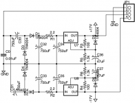
Here's the schematic for the power supply board. It's designed to work with an external wall wart that outputs AC on a standard barrel connector.
Pin 2 on the jumper brings in 12 VAC (and I might reduce that to 9 VAC).
Pins 3 and 4 return +17.5 V (16.8 V to 18.2 V) and -17.5 V to the main board.
There are 100 µF capacitors on the main board, where I thought they would be more effective, but that basically means I can't test this power supply board without a load attached. Actually, I tested with 47 µF capacitors because that's what fit (limited space for larger diameters).
Hmm, I should check the current draw of my main board to make sure it's under 100 mA...
Attachments
- Status
- This old topic is closed. If you want to reopen this topic, contact a moderator using the "Report Post" button.
- Home
- Amplifiers
- Power Supplies
- Troubles with Texas Instruments LM337LZ