Hello,
I've been asking for help on the AV forums about fixing my JVC and I've been directed here. The thread over there is this one:
Fixing JVC UX-D427S? | AVForums
I'm a bit out of my depth, to be honest but I have a soldering station and I'm willing to use it.
To summarise, my JVC UX-D427S valve-driven mini hi-fi has stopped working - apparently suffering a power supply problem. The hi-fi would power up, but the LCD would be dim in patches, the valves would flicker, there would be an audible slow tick and it would switch off with a pop when you tried to do anything.
It was suggested that a rectifier on heat sink on the power supply board may have burnt out, which sound logical, so I purchased and replaced a rectifier and a mosfet, both of which were screwed to heat sinks on the power supply board. Sadly this didn't fix the problem, however I realised the ticking noise seemed to be coming from this transformer:
Imgur: The magic of the Internet
I did a bit more random googling, and I've found a random suggestion that it could be due to the transformer 'bootstrap' circuit malfunctioning, preventing the transformer from powering itself... or something like that.
Does anyone know what the problem might be? I'm loathe to just chuck it away when it might be fixed by soldering a £2 component in place!
Many thanks,
ND
Last edited:
Bootstrap...
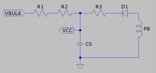
Generally the control ICs used on offline power supplies have something called an Under Voltage Lockout, UVLO.
The supply has to rise above some level, e.g. 12V, before the IC wakes up. Having woken up the IC will go back to sleep if its supply falls below some other level, e.g. 9V.
Start up is via R1/R2 which bleed current from the bulk voltage, rectified mains, which charges CS. R1/R2 are high values, 220K, and you need two/more to satisfy their voltage ratings.
When VCC hits 12V the IC wakes up. The transformer has a Power Back winding, PB, which begins to supply power via D1/R3 to CS. D1 is likely a small signal diode and R3 will be something like 22R.
If D1/R3 go AWOL, broke, then the circuit, transformer, will sit there going tick, tick, tick as it cycles through UVLO.
This might not be the source of your problem given your description of the thing being able to start up and go through pre-heat although it is feasible that even though it is cycling that may sufficient to power a minimal load.
...
Attachments
Hello Morbid Fractal,
Thank you very much for your response - I did find something similar while googling, which referred to a weak diode possibly being the source of the problem.
I did identify a diode next to the transformer and also a large resistor just next to it:
Imgur: The magic of the Internet
however I'll have to pull the circuit back out again and see if I can work out which might be R1/R2/R3. On the plus side, these are easy components to desolder and check!
Thank you very much, you've given me a good lead to work with!
ND
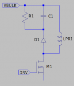
Those components are likely to be... are a clamp for transformer reset. The circuit is probably a single switch flyback.
D1 is a UF400X. C1 looks to be a green mylar capacitor. R1 looks like a 2W MF.
The electrolytic would be more likely to be the IC supply filtering capacitor.
...
D1 is a UF400X. C1 looks to be a green mylar capacitor. R1 looks like a 2W MF.
The electrolytic would be more likely to be the IC supply filtering capacitor.
...
Attachments
Ok, wow - learning a lot here!
What's the electrolytic? That's the only part you mention I can't identify.
Do you think the clicking may still be the result of the transformer cycling, and that the diode might be the component that's failed?
Many thanks!
ND
What's the electrolytic? That's the only part you mention I can't identify.
Do you think the clicking may still be the result of the transformer cycling, and that the diode might be the component that's failed?
Many thanks!
ND
Cylindrical thing with a black plastic sleeve. Will be something like 22uF-47uF 25V rated. Given the supply does try to start it is probably OK.
Blue disks will be class Y ceramic capacitors used to control noise in particular the pair primary to secondary. The other thing visible in one of your photographs, 4 pin DIP, is an opto-isolator which will be part of the voltage feedback/regulation loop.
I assume the board is double sided and the interesting stuff will be on the other side... lots of surface mount bits and pieces.
If the start up circuit is the problem then diodes tend to fail short whilst resistors fail open. A short diode would prevent the circuit from initially charging so it is more likely to be the resistor.
Oh... I'm not sure but C7, blue disk, and L4, bead inductor, might form part of a resonant circuit on the Drain/Primary connection. It's not something I have implemented myself but some circuits make use of quasi-resonant operation which senses a minima in the Drain voltage to initiate the next switching cycle helping to reduce losses. If you can identify the control IC you will get a better idea about how things might be implemented.
The ticking of the transfo is usually caused by a overload (or shot cicuit) of the supply.
It starts-up find an overload, shuts down and restart, tic ... tic ... tic ...
If it does that without a load, check for shorted diodes and/or electrolytic on the secondairy side.If there are multiple loads deconnect one at the time to see if the ticking stops.
Mona
It starts-up find an overload, shuts down and restart, tic ... tic ... tic ...
If it does that without a load, check for shorted diodes and/or electrolytic on the secondairy side.If there are multiple loads deconnect one at the time to see if the ticking stops.
Mona
Oh... I'm not sure but C7, blue disk, and L4, bead inductor, might form part of a resonant circuit on the Drain/Primary connection. It's not something I have implemented myself but some circuits make use of quasi-resonant operation which senses a minima in the Drain voltage to initiate the next switching cycle helping to reduce losses. If you can identify the control IC you will get a better idea about how things might be implemented.
Ok, I'll grab a photo of the underside of the board when I get a chance. It's not that exciting though! I was surprised how sparse it was - just a half-dozen small chips, two or four pin mostly. I suspect even if I could identify that IC, I'm not sure it would mean very much to me!
Is it still worth me desoldering and checking the diode and resistor?
Many thanks,
ND
The ticking of the transfo is usually caused by a overload (or shot cicuit) of the supply.
It starts-up find an overload, shuts down and restart, tic ... tic ... tic ...
If it does that without a load, check for shorted diodes and/or electrolytic on the secondairy side.If there are multiple loads deconnect one at the time to see if the ticking stops.
Mona
The transformer doesn't tick without a load - when you switch on the power at the wall (standby LED glowing) you can't hear anything. It's only when you try to power-up the unit that the ticking begins. Does that mean anything?
Many thanks,
ND
Yes, the load can be to heavy or has a big capacitor on the power, some SMPS won't start-up properly as the capacitor looks like a short circuit at the start.The transformer doesn't tick without a load - when you switch on the power at the wall (standby LED glowing) you can't hear anything. It's only when you try to power-up the unit that the ticking begins. Does that mean anything?
Another possebility is a fault in the current sensing of the supply.
Mona
Ok, finally got round to checking the big resistor mentioned before and the little diode.
The resistor measured at 47.2Kohm, pretty much spot on spec.
The diode read as closed in one direction, and gave a .47 voltage drop in the other direction, although I did this without removing it from the circuit but I did discharge all the capacitors on the board with a screwdriver before doing the measurements.
Here's both sides of the board in its entirety (as you can see I need more practice with my soldering!) Any ideas which random component to try next?
[Imgur](https://i.imgur.com/VITwf6n.jpg)
[Imgur](https://i.imgur.com/53gkbsA.jpg)
Many thanks for all your help so far, I keep hitting dead-ends but it's all progress!
Last edited:
- Status
- Not open for further replies.
- Home
- Amplifiers
- Power Supplies
- Fixing JVC UX-D427S....