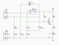
I've designed an adjustable regulated supply for the screen grids in a EL34 PP amplifier. I don't plan to adjust the voltage more than 35v from the supply, so an LM317 will do fine.
I've been looking through the forums and noticed a lot of people building "Maida" regulators. This is a design from an application note that allows variation over the entire voltage range. This it not what I need and I assume not what most people implementing this circuit need either... so why?
Obviously I have protective Zeners to allow the capacitive loads to charge on startup. I don't see the need to add an emitter follower to my circuit though. Maximum power dissipation from the LM317 is less than 2W. I'm making a small PCB and plan to use a DPAK and solder it to the VCC plane as heatsink.
I'm about to place the order and thought I ask to to if I'm missing something here. I can post the design if anyone is interested.
Thanks!
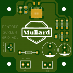
Minor update to the circuit. Nominal input (pin1 of TB1) is 440v. Output (pin2 of TB1) is adjustable from 3 to 35ish volts from the input. RV1 provides a range from 388v to 464v to allow for variations in the input. For 440v the usable range would be 405-437v
Attachments
- Status
- This old topic is closed. If you want to reopen this topic, contact a moderator using the "Report Post" button.