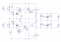
I have designed a dual rail psu using Livewire which connects to my pcb design cad for autoroute pcb designs, I don't use it normally as in makes a mess of the wiring.
I have searched the internet for these designs & never found this one I had in my mind for quite a while, the simulation on Livewire says it is working perfect when you adjust the sliders both rails will go down to 500mv at their lowest as anything below that & the output goes crazy (just like real life), so that is why I added the 5k resisters to the circuit.
The input voltages to the circuit are stabilized from a main psu box so this is the 2nd stage regulation unit & am now wondering what improvements could be added to this circuit prior to building & testing of it ?
Thanks for any input you have in advance
J247W
Attachments
I see lots of questionable or suboptimal aspects to this design.I have designed a dual rail psu using Livewire which connects to my pcb design cad for autoroute pcb designs, I don't use it normally as in makes a mess of the wiring.
I have searched the internet for these designs & never found this one I had in my mind for quite a while, the simulation on Livewire says it is working perfect when you adjust the sliders both rails will go down to 500mv at their lowest as anything below that & the output goes crazy (just like real life), so that is why I added the 5k resisters to the circuit.
To name a few: the use of a comparator in an opamp role.
It can work, but with many caveats, and when it's done, it's generally as a way to use spare operators of a package to save an opamp, but I would certainly never do this as a first instance: there are so many cheap and good opamps around that it is a really masochistic approach.
If you absolutely want to stick to it, you have to include proper compensations, and the 10µ output cap is certainly not going to do it, in fact it will make the job almost impossible.
The reference source is also extremely poor: a zener based shunt reg. directly sourced from the raw input will yield an atrocious line regulation, and the 1000µ across the zener is mostly wasted, because of its low impedance.
A LM337/317 pair would make a much better job, and would also be cheaper and simpler. They would be current and dissipation protected too.
They would not be able to go below 1.25V in a simple implementation, but that shouldn't be too much of a problem, since you tolerate it for your current version.
BTW, with proper opamps and compensations, your circuit could in principle reach 0V (even with a LM339, but there is a lot of work ahead).
Note that the datasheet and applications of the 339 show ways of using it as a low frequency opamp, but adapting those techniques to your regulator is going to be complicated...
I see lots of questionable or suboptimal aspects to this design.
To name a few: the use of a comparator in an opamp role.
It can work, but with many caveats, and when it's done, it's generally as a way to use spare operators of a package to save an opamp, but I would certainly never do this as a first instance: there are so many cheap and good opamps around that it is a really masochistic approach.
If you absolutely want to stick to it, you have to include proper compensations, and the 10µ output cap is certainly not going to do it, in fact it will make the job almost impossible.
The reference source is also extremely poor: a zener based shunt reg. directly sourced from the raw input will yield an atrocious line regulation, and the 1000µ across the zener is mostly wasted, because of its low impedance.
A LM337/317 pair would make a much better job, and would also be cheaper and simpler. They would be current and dissipation protected too.
They would not be able to go below 1.25V in a simple implementation, but that shouldn't be too much of a problem, since you tolerate it for your current version.
BTW, with proper opamps and compensations, your circuit could in principle reach 0V (even with a LM339, but there is a lot of work ahead).
Note that the datasheet and applications of the 339 show ways of using it as a low frequency opamp, but adapting those techniques to your regulator is going to be complicated...
I agree wholeheartedly with ELvee. I have tried to use a 339 for an op amp just because I have a bunch of them. It was a useless effort. Comparators are different than op amps so lets just use them where they are intended.
Elvee is also correct, this is just a bad circuit design. Give it up and use the three terminal regulators. However if you need really low noise the 723 will treat you better. If the current you need is low, the 723 has a built in pass transistor. The application is really easy. You can filter the refernce for low noise and the internal op amp tends to be low noise in most samples.
I have achieved 2 uv of output noise A wtd with this part. As in all parts, some makers and some batches are better than others for noise.
LM339 is not an opamp. It is an Open Collector comparator.
If your simulation says an LM339 works at IC2a, it is wrong.
IC2b at least has current going the right direction to turn-on Q2. But the comparator is not stable under NFB. They show it "stable" with a heavy cap on the '339 output; the 10uFd on the far side of Q2 is not nearly enough. Also Q2 will turn-off poorly, nothing to drain leakage or stored charge. Together, it will squegg.
Use real opamps.
There's no protection for the precious TIP4xes. I remember when they were worth 2 hours pay. Today their death may be no-cry, but still annoying. Protection can be contrived but is not so simple. _I_ would use LM317 type low-V regulator chips; hard to kill.
The one output is *usually* the inverse of the other. In those cases, one side should just be an inverter.
You can do better. You can copy better.
LM339 is not an opamp. It is an Open Collector comparator.
If your simulation says an LM339 works at IC2a, it is wrong.
IC2b at least has current going the right direction to turn-on Q2. But the comparator is not stable under NFB. They show it "stable" with a heavy cap on the '339 output; the 10uFd on the far side of Q2 is not nearly enough. Also Q2 will turn-off poorly, nothing to drain leakage or stored charge. Together, it will squegg.
Use real opamps.
There's no protection for the precious TIP4xes. I remember when they were worth 2 hours pay. Today their death may be no-cry, but still annoying. Protection can be contrived but is not so simple. _I_ would use LM317 type low-V regulator chips; hard to kill.
The one output is *usually* the inverse of the other. In those cases, one side should just be an inverter.
You can do better. You can copy better.
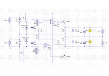
Thank you for your informative reply.
See attached image for improved circuitry which runs stable in simulation as only have a limited choice of ic's, as for output caps the "sim" does not like 1,000uF caps as the output. (could programming error or my outdated program ?)
The circuit is only 18vdc reg coming in so if the output goes full voltage this should not affect the circuit it is being used for. (also yet again my "sim" only shows 9v zenner as the highest voltage I can select)
This is also for anyone but can you show improvements as an image please ?
As for the op-amps +- at the inputs, is this not how they should be or the negative rail op-amp would not switch the PNP transisters on ?
I have changed the op-amps to a single package per rail now.
Regards
J247W
Attachments
J247W,
Why the triple darlington on the op amps? its not needed and there are no emitter to base resistors to deal with leakage currents.
Why that op amp when a a TL071 or any common op amp will do.
This is gettin worse, not better. Did you look at the LM723 yet.
There is still no short circuit protection, zeners are still on the unreg side, you will run out of common mode range on the top op amp at 2.5 volts making that your minimum.
My question is why are you interested in this horrible circuit?
What are your voltage and current requirements?
Thank you for your informative reply.
See attached image for improved circuitry which runs stable in simulation as only have a limited choice of ic's, as for output caps the "sim" does not like 1,000uF caps as the output. (could programming error or my outdated program ?)
The circuit is only 18vdc reg coming in so if the output goes full voltage this should not affect the circuit it is being used for. (also yet again my "sim" only shows 9v zenner as the highest voltage I can select)
This is also for anyone but can you show improvements as an image please ?
As for the op-amps +- at the inputs, is this not how they should be or the negative rail op-amp would not switch the PNP transisters on ?
I have changed the op-amps to a single package per rail now.
Regards
J247W
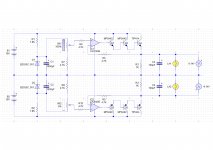
It seems to me that the neg circuit has positive feedback instead of nfb and will immediately latch up to max output when switched on.
If it runs fine in sim I'd like to see the output curves.
Google 'superregulator', if you are serious about the performance.
Jan
+1 (agree with this question).J247W,
My question is why are you interested in this horrible circuit?
To be fair, it may look horrible to those of us who have been designing and building such circuits for ages. But I understand he came up with this on his own and that is respectable. How many of you would come up with it if you had never seen one?
Nevertheless, Google is your friend and he could have saved himself a lot of work and disappointment just by searching the 'net for stabilized power supplies. There must be a million of them around, all beating the same drum.
Jan
Nevertheless, Google is your friend and he could have saved himself a lot of work and disappointment just by searching the 'net for stabilized power supplies. There must be a million of them around, all beating the same drum.
Jan
"Why that opamp" - he said his sim offers limited choice. Mine only has LF411, so I get it.
Mine also only gives me a 5V Zener, but I can Edit Model and put in any number. However the regulator can be gained-up to take 5V or 7V and make it 10V, 14V, or any output.
The triple Darlington does seem excessive. Any general purpose opamp will give 10mA, any good transistor hFE of 50, so you get to a half-Amp in a single stage. We rarely need more than that in a regulated supply.
The LM723 is VERY old, was not that good, and seems to cost $12 at reputable distributors. If you must maintain a $1M factory machine from 1979, $12 for a drop-in is cheap. But in new design, "not recommended". (Also, negative outputs were always a pain.)
+1 on Google. It may be a thrill to self-invent a design, it is wise to benefit from the mistakes of those who went before us.
It is nice to see all these replies although very patronising but it helps me add you all to my ignore list, thanks I know what I am doing, if you were real engineers you would discuss things properly but guess as your all bit snobby towards circuits which come out of good books.
It seems to me that the neg circuit has positive feedback instead of nfb and will immediately latch up to max output when switched on.
If it runs fine in sim I'd like to see the output curves.
Google 'superregulator', if you are serious about the performance.
Jan
I believe Jan is correct about the negative supply.
TO the OP>
Though I still dont care for either the plus of minus circuit if you do have two independent power sources why not just make two identical regulators and then connect them in the desired polarities.
Once again the 723 will solve all your problems with fewer parts, short protection, low noise, great regulation.
http://www.ti.com/lit/ds/symlink/lm723.pdf
see page 2 for the hookup. 4 resistors, 2 small caps, excellent performance. It has all the elements of your circuit just done properly.
While I can understand that you want to ignore some of these replies my intent is to be helpful. I dont use simulations at all, I build the circuit and get into what is going on. Simulations only make sense when all the data and models are correct. For instance are you using batteries for the input, if not what is the ripple on the main filters?
Your positive regulator circuit is fine. Build it, measure it and improve it on the bench. See how closely the simulations predict the actual operation. Once you get it working and understand it build the negative one. I believe Jan is correct and it will latch up. I am surprised that the simulation did not point that out the following.
1. the missing base to emitter resistances will turn the transistors on FOR SURE. If not at room temp they will when things heat up. Does the simulator assume transistors with zero leakage?
2. The negative supply simulation should not even give output data and should latch up as Jan kindly pointed out.
3. What is the range of input voltages and what is the output current.
Last edited:
The LM723 is VERY old, was not that good, and seems to cost $12 at reputable distributors. If you must maintain a $1M factory machine from 1979, $12 for a drop-in is cheap. But in new design, "not recommended". (Also, negative outputs were always a pain.)
+1 on Google. It may be a thrill to self-invent a design, it is wise to benefit from the mistakes of those who went before us.
You must be looking up a metal can 723, of course its obsolete and expensive. Look up the 14 pin Dip. Its less than 50 cents. Because of ROHS its a little harder to find the current part UA723 is easier to find, that's the early part number from Fairchild who created it. The non ROHS ones are obsolets but both DigiKey and Newark have plenty. UA723CN Texas Instruments | Integrated Circuits (ICs) | DigiKey
Mouser has 14,000 of the surface mount UA723CD Texas Instruments Linear Voltage Regulators | Mouser and 1700 of the DIP with quotes up to 10,000 pcs. UA723CN Texas Instruments Linear Voltage Regulators | Mouser Hardly obsolete or expensive.
When a part does just what a part needs to do then it does it Some things do not need to be improved. This part will go on long after you and I are dead.
Obviously you have no knowledge of this fine IC which is still being taught in classes today. See this Quora link. Six engineers supporting the teaching of this specific part.
Why is my teacher still teaching the LM723 voltage regulator? It is older than he is.? - Quora

Last edited:
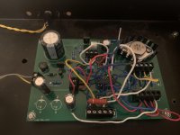
I would like to pay homage to the late Roger Modjedski by seconding His use of
The venerable uA723 it is very easy to implement, 6 resistors at most 2 or more caps, and a pass device being the most expensive. His Music Reference RM-4 is a great example of the use of the 723, a very low noise PS. The key is a zener stabilized PS for the chip, or a pre-regulator in LT supplies, and a low pass filter on the reference, and bypassing the feedback resistors, a 4.7uf sufficient.
2uV output noise spec is well within range. Below is an example of a protoboard for the 723. This is wired for ~245VDC will post schematic as well.
Attachments
Last edited:
- Status
- This old topic is closed. If you want to reopen this topic, contact a moderator using the "Report Post" button.
- Home
- Amplifiers
- Power Supplies
- Dual Rail PSU Voltage Stabilized By Op-Amps