Hello,
I was looking at some commercial IEC filters with an intention to clone them. My understanding is that even if the schematics are available, the lay out and actuall construction might be critical for performance so this would be a good reason to buy the ready products. But my little research left me with more questions about how to choose them. In particular, among the models for different current consumption, the only thing that change is the inductor's value: as the current goes up inductance goes down. I suppose it has to do with inductor's saturation but anyway how do we choose the proper filter for a given device? If, for example, the current consumption is at 1A then filters rated at 3A and 10A would perform differently?
I also found datasheets stating inductance at a certain frequency. What would that mean? Does inductance change with frequency?
look here 1st https://www.schaffner.com/fileadmin...ation_note/Schaffner_AN_RB_common_chockes.pdfHello,
In particular, among the models for different current consumption, the only thing that change is the inductor's value: as the current goes up inductance goes down. I suppose it has to do with inductor's saturation but anyway how do we choose the proper filter for a given device? If, for example, the current consumption is at 1A then filters rated at 3A and 10A would perform differently?
Remember the key is essentially they are all LCR low pass filters. Most of the attenuation is common mode, but they do have a differential measurement as well . Within the same filter series, the magnetic core usually remains the same size, so a 1 Amp part will allow more wire turns, more turns of wire = higher inductance & I^2*R heat losses, (but sometimes at the risk of lower self resonance frequency) than their higher rated current brothers. Performance is compared by looking at the stop band attenuation for the frequencies of interest for your device. Besides CM stop band attenuation there is , insertion loss, good high frequency atten. most require shielding cans and proper component lead dressing, don't forget safety is very important ( fire and shock ).
Common mode inductance is fairly constant over current and frequency, unlike the differential mode.I also found datasheets stating inductance at a certain frequency. What would that mean? Does inductance change with frequency?
Last edited:
The link is great! A first read answered almost all my questions. It also puts me back to the diy approach. I'll take the time to read it more thoroughly. Many thanks Infinia!
Hello again!
I spent some time reading the paper linked above and it was quite helpful to clear some things in my mind. I understand that for a given noise target - of known frequency and magnitude measured or just estimated - that needs to be attenuated to a level that complies with the IEC norms, and knowing that the filter's attenuation is rising 40dB per decade, we have to set the corner frequency of the filter (-3dB) so that it will have the "room" to reach the target. All that provided that the inductor will have a self resonance frequency higher than the noise and it will not saturate, so its behavior will be predictable. Trying to find some real life examples, I used the equations to do a reverse engineering to some commercial products. I see some of them setting a corner frequency well within the audio spectrum while others keep it much higher at 60kHz and above. So, I need to ask if is there any problem to set the corner in audio frequencies or should we keep it above 20kHz? (or more?)
I spent some time reading the paper linked above and it was quite helpful to clear some things in my mind. I understand that for a given noise target - of known frequency and magnitude measured or just estimated - that needs to be attenuated to a level that complies with the IEC norms, and knowing that the filter's attenuation is rising 40dB per decade, we have to set the corner frequency of the filter (-3dB) so that it will have the "room" to reach the target. All that provided that the inductor will have a self resonance frequency higher than the noise and it will not saturate, so its behavior will be predictable. Trying to find some real life examples, I used the equations to do a reverse engineering to some commercial products. I see some of them setting a corner frequency well within the audio spectrum while others keep it much higher at 60kHz and above. So, I need to ask if is there any problem to set the corner in audio frequencies or should we keep it above 20kHz? (or more?)
Hi. So, I need to ask if is there any problem to set the corner in audio frequencies or should we keep it above 20kHz? (or more?)
Remember undesirable RF or HF interferences can combine or be converted in-band (Eg. baseband or audio ) by any circuits non linearity. So mixing 'spurs at RF frequencies or those close enough so the difference is within 20,000 or less can be processed same as the desired audio signals. ..eg reduction of SN.
Choosing cutoff frequencies? I'm pretty sure its like anything else.. a trade-off mostly by constraint of size , cost rather than by looking at attenuation charts then arbitrarily choosing a too low of cutoff to which then cannot be reached by anything practicable (>50dB forget it). Also consider the testing source and load impedance don't scale precisely anyway.
Id do a few design cuts on some magnetic cores you want to use, Get a practicable handle on the magnetics designs. then most folks choose to cascade 2 pole LPF stages as you can only get 40-50 dB per stage (unless extra shielding) for the more pessimistic applications.
Last edited:
Hi
Thanks for reply
Yes, that's something I wanted to ask too. The conclusion is that even if we start from too low there isn't enough bandwidth for high attenuation. I just don't know how much attenuation would be sufficient. (For usual kinds of noise in an ordinary environment if this does make any sense) If we need to attenuate significant noise level at say 30-70kHz, then cascaded filters seem the only way. But do we need to reach that low? This is supposed to be noise coming from SMPS that incorporate their own properly designed filters, or at least they should. The same for digital circuits. I was thinking about the noise sources that are not being filtered at the first place, RF picked up from the mains rails, and the not so smart devices such as refrigerators, ovens, hair dryers and the alike, but I need to gather more information about that.
I'm not sure I can understand this. If it is about IMD then I get the meaning. The lower harmonics of the noise will be processed as audio signal by the amp.
But the upper frequencies of the audio signal could be attenuated by the filter's (low) cut off?
Thanks for reply
Hi
Choosing cutoff frequencies? I'm pretty sure its like anything else.. a trade-off mostly by constraint of size , cost rather than by looking at attenuation charts then arbitrarily choosing a too low of cutoff to which then cannot be reached by anything practicable (>50dB forget it). Also consider the testing source and load impedance don't scale precisely anyway.
Id do a few design cuts on some magnetic cores you want to use, Get a practicable handle on the magnetics designs. then most folks choose to cascade 2 pole LPF stages as you can only get 40-50 dB per stage (unless extra shielding) for the more pessimistic applications.
Yes, that's something I wanted to ask too. The conclusion is that even if we start from too low there isn't enough bandwidth for high attenuation. I just don't know how much attenuation would be sufficient. (For usual kinds of noise in an ordinary environment if this does make any sense) If we need to attenuate significant noise level at say 30-70kHz, then cascaded filters seem the only way. But do we need to reach that low? This is supposed to be noise coming from SMPS that incorporate their own properly designed filters, or at least they should. The same for digital circuits. I was thinking about the noise sources that are not being filtered at the first place, RF picked up from the mains rails, and the not so smart devices such as refrigerators, ovens, hair dryers and the alike, but I need to gather more information about that.
Remember undesirable RF or HF interferences can combine or be converted in-band (Eg. baseband or audio ) by any circuits non linearity. So mixing 'spurs at RF frequencies or those close enough so the difference is within 20,000 or less can be processed same as the desired audio signals. ..eg reduction of SN.
I'm not sure I can understand this. If it is about IMD then I get the meaning. The lower harmonics of the noise will be processed as audio signal by the amp.
But the upper frequencies of the audio signal could be attenuated by the filter's (low) cut off?
You set the filter bandwidth to reduce whatever it is that you need to reduce. For a passive filter of a finite size there is a tradeoff between attenuation and bandwidth. Each filter section will do a certain amount of each. You then cascade sections to get either greater bandwidth (sections differ) or greater attenuation (sections the same).
Thanks DF96! Is it OK if we cascade filters for a sharper roll off always keeping in mind audio applications? I have a rough understanding of how things work in speakers crossovers but here I can't understand if phase would be an issue. Of course, I'm asking about what theory could predict.
Yes, you can cascade filters. It is not the sharper rolloff which matters, but the deeper attenuation (if the filters cover the same frequency band). Phase is not an issue; you are filtering the power supply input, not the audio signal.
First time I feel I'm not going blind into this. Thank you Infinia and DF96! There is a schematic that is slowly taking shape in my mind. I'll report progress.
Hello, I'm returning to this.
I did some internet reading. There's a lot of information out there that I think I can understand better now. I found this http://www.mouser.com/pdfDocs/schaffner-engineers-guide-designing-emi-filters1-13-17.pdf and this EMC FILTERS: Design, Selection and Installation of Power and Signal lines filters « Electronic Environment to be very helpful. Bellow is my interpretation of all this, not unlikely to be mistaken. Feel free to comment please.
As it was pointed in previous posts, there are compromises in the implementation of an EMI filter. Starting from the source- load impedance ratio, mains and transformers won't be anywhere close to the 50/50 ohm system typically used for performance evaluation. Manufacturers provide info about 1/100 ohm and 100/1 ohm and it seems that when the source impedance is much lower than the load we stay closer to the 40dB per decade rising attenuation model. If I understand correctly, mains impedance should be bellow 1 ohm and the transformer's primary impedance for home audio should be around a few hundreds ohm.
There is a rule of thumb according to which the low impedance side of the filter should see an inductor and the high impedance side see a capacitor. That restricts us to 2nd and 4th order filters.(mains>LC or LCLC>transformer) I tried to find the calculations for the 4th order but Butterworth polynomials are beyond my reach. From what DF96 replied I'm making a thought that a 4th order filter can be seen as two 2nd order(?) Is that simple to calculate the cutoff frequency and attenuation of each one? Even so, I came to the conclusion that a 4th order won't do much more vs a 2nd order because the total capacitance of the filter must stay within the safety standards for leakage current. I wasn't able to find exact numbers for that. If I got it right, it is 0,5mA for USA and 3,5mA for EU, for power cord connected devices. Confusion derives from the tolerance limits. The formula is I leak= 2π*f*V*Cy where f and V are the mains frequency and voltage. So the y capacitors must be max 11nF for USA and 47nF for EU. My magic bus is unlikely to have a trip across the Atlantic ocean so I'll stick with the 47nF. The difference between the standards is interesting. Perhaps it has to do with the different mains distribution networks. I can't tell.
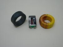
What about the chokes? There is a "debate" for the core material; nanocrystalline vs MnZn ferrite. Nanocrystalline gives significantly higher inductance with less wire turns. That means more compact dimensions and lower stray capacitance i.e. very high resonance frequency. The catch is in its relative permeability. I will start falling very early and at the frequencies of interest only a small fraction of its nominal inductance is left. This point is not so clear to me though. It's supposed that in a common mode choke the magnetic flux is canceled so inductance is close to zero. Apparently, the imbalance between the two halves of the choke increases as frequency goes up. So, to answer my own question, choke's inductance does change with frequency because of the core's relative permeability. The MnZn ferrite is more predictable up to the MHz region. I found some toroid ferrites at a good price and with 33 turns of 1mm (AWG 18) motor wire I get 8,2mH.(Attached pic) DCR is hardly 0,1 ohm and stray capacitance non measurable with my DMM that goes down to pF. The resonance frequency should be sufficiently high I think.
The cutoff frequency for 8,2mH and 47nF is 5735Hz. Ideally 40dB attenuation at 57kHz - hopefully something close to that in real life - and 80dB at 570kHz. How do I find the attenuation at say 70kHz and 150kHz? I'm not good with dB. Is it a linear increase?
To answer another question of mine, if it would matter to set the cutoff frequency in the audio spectrum. I realized that the engineers didn't bother to answer that because there isn't any question. There is no audio in the primary of a power transformer, only 50/60Hz mains which should not be affected by any means of impedance. Thinking of it the other way around, power transformers are not optimized to pass 20-20.000Hz.
Long post! There will be another one about the kind of noise I'm chasing. I hope I'm not wasting your time with nonsense. You can take all the time you need if you wish to correct any of my misunderstanding on the subject.
I did some internet reading. There's a lot of information out there that I think I can understand better now. I found this http://www.mouser.com/pdfDocs/schaffner-engineers-guide-designing-emi-filters1-13-17.pdf and this EMC FILTERS: Design, Selection and Installation of Power and Signal lines filters « Electronic Environment to be very helpful. Bellow is my interpretation of all this, not unlikely to be mistaken. Feel free to comment please.
As it was pointed in previous posts, there are compromises in the implementation of an EMI filter. Starting from the source- load impedance ratio, mains and transformers won't be anywhere close to the 50/50 ohm system typically used for performance evaluation. Manufacturers provide info about 1/100 ohm and 100/1 ohm and it seems that when the source impedance is much lower than the load we stay closer to the 40dB per decade rising attenuation model. If I understand correctly, mains impedance should be bellow 1 ohm and the transformer's primary impedance for home audio should be around a few hundreds ohm.
There is a rule of thumb according to which the low impedance side of the filter should see an inductor and the high impedance side see a capacitor. That restricts us to 2nd and 4th order filters.(mains>LC or LCLC>transformer) I tried to find the calculations for the 4th order but Butterworth polynomials are beyond my reach. From what DF96 replied I'm making a thought that a 4th order filter can be seen as two 2nd order(?) Is that simple to calculate the cutoff frequency and attenuation of each one? Even so, I came to the conclusion that a 4th order won't do much more vs a 2nd order because the total capacitance of the filter must stay within the safety standards for leakage current. I wasn't able to find exact numbers for that. If I got it right, it is 0,5mA for USA and 3,5mA for EU, for power cord connected devices. Confusion derives from the tolerance limits. The formula is I leak= 2π*f*V*Cy where f and V are the mains frequency and voltage. So the y capacitors must be max 11nF for USA and 47nF for EU. My magic bus is unlikely to have a trip across the Atlantic ocean so I'll stick with the 47nF. The difference between the standards is interesting. Perhaps it has to do with the different mains distribution networks. I can't tell.
What about the chokes? There is a "debate" for the core material; nanocrystalline vs MnZn ferrite. Nanocrystalline gives significantly higher inductance with less wire turns. That means more compact dimensions and lower stray capacitance i.e. very high resonance frequency. The catch is in its relative permeability. I will start falling very early and at the frequencies of interest only a small fraction of its nominal inductance is left. This point is not so clear to me though. It's supposed that in a common mode choke the magnetic flux is canceled so inductance is close to zero. Apparently, the imbalance between the two halves of the choke increases as frequency goes up. So, to answer my own question, choke's inductance does change with frequency because of the core's relative permeability. The MnZn ferrite is more predictable up to the MHz region. I found some toroid ferrites at a good price and with 33 turns of 1mm (AWG 18) motor wire I get 8,2mH.(Attached pic) DCR is hardly 0,1 ohm and stray capacitance non measurable with my DMM that goes down to pF. The resonance frequency should be sufficiently high I think.
The cutoff frequency for 8,2mH and 47nF is 5735Hz. Ideally 40dB attenuation at 57kHz - hopefully something close to that in real life - and 80dB at 570kHz. How do I find the attenuation at say 70kHz and 150kHz? I'm not good with dB. Is it a linear increase?
To answer another question of mine, if it would matter to set the cutoff frequency in the audio spectrum. I realized that the engineers didn't bother to answer that because there isn't any question. There is no audio in the primary of a power transformer, only 50/60Hz mains which should not be affected by any means of impedance. Thinking of it the other way around, power transformers are not optimized to pass 20-20.000Hz.
Long post! There will be another one about the kind of noise I'm chasing. I hope I'm not wasting your time with nonsense. You can take all the time you need if you wish to correct any of my misunderstanding on the subject.
Attachments
In a typical mains filter there are two sets of capacitors: line to neutral, and both to ground. It is only the 'both to ground' capacitors which must be limited in value in order to limit leakage current. I thought the EU limit was 1mA per device - you can feel 0.5mA. You don't want to be injecting too much current into the ground connection.
The reason for two sets of capacitors is that you have two types of interference to filter: common-mode and differential mode.
The reason for two sets of capacitors is that you have two types of interference to filter: common-mode and differential mode.
Yes, I understand the function of the capacitors. The X type from line to neutral is part of the differential mode filter. Its value is limited only by how much power it would be allowed to consume. I've seen some formulae about this. But anyway it will be around 1μF. The EU limits regard the Y type capacitors to ground that are part of the common mode filter. I didn't manage to find anything specific. US set this at 0,5mA. But then it can be deviated as long as there is a warning label on the device(?) EU standards seem to be more loose. I was puzzled but then my experience from daily practice is that any device connected to mains PE will stay to zero until the limit that triggers the safety circuit breakers is reached. I may be wrong. Perhaps it's not the same with all mains distribution networks. We have a TT system. There are other types too. Earthing system - Wikipedia
Commercial EMI filters adopt the 0,5mA limit to cover all standards. But perhaps a DIY filter for personal use could stretch the limits for the actual environment?
Commercial EMI filters adopt the 0,5mA limit to cover all standards. But perhaps a DIY filter for personal use could stretch the limits for the actual environment?
I really don't know... Here's a very simple thought; It's all about the current that flows from the chassis to ground. An amplifier that holds such a filter would affect other devices in the same network? Do all these currents add? What if we place the filter inside a separate box with its own PE connection - and make it work for RF - and run the power cord from there to the amplifier?
Yes, these currents add. If the PE gets broken then these currents could go to ground through a user, which is another good reason to keep them small.
Understood. So for leakage current 0,5mA and 230V/50Hz mains the Y capacitors can be max 6,8nF. Combined with my 8,2mH chokes the cutoff frequency is 15kHz. For 1mA it's 14nF and 10kHz. My system consists of a PC, a monitor, a DAC, a preamp and an amp often two monos. That's a total of 5 or 6. It will be something between 2,5 and 6mA to ground.
I treat PE as if it is random to begin with. No sense allowing it to get caught up in out circuits.would affect other devices in the same network?
You may think that I should had started the thread with this post but I really had rejected the diy option and was looking to buy something off the shelf. Now thanks to the contributors, I have a better understanding of it and I'm thinking to give it a try. The schematic and component's values are pretty much "fixed". Still have queries about the nature of the EMI noise though.
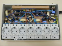
Many years ago I've built a diy EMI filter found on the internet. You can see it in the first picture. Don't be confused with the electrolytic capacitors; these are part of a DC blocker. The basic filter is 100nF line to neutral/27nH common mode/6,8nF to ground/275V MOV. One of the first upgrades I did was to replace the caps with proper X and Y types so go figure. Back then I had no clue how this thing works but it didn't take too long to understand that not much was to be expected from it. I kept it serving as a power strip and that was all. Or was it?
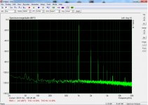
Lacking of serious bench equipment, I was convinced that I had no chance to measure anything about EMI yet I managed to spot one and only case in a simple FFT. The second picture shows the graph of a tube preamp with linear psu and no mains filter. In the third picture is the preamp together with a vacuum cleaner, again no filter. You can see the peaks at 6,8kHz and 13,6kHz. These come always with the vacuum cleaner, no other appliance at home does anything similar. For your information, another preamp, solid state with high tech regulated psu is completely immune to this noise. But what is this noise? The vacuum cleaner has a very long power cord with only two wires, no ground. Taking the plug to a distant outlet while not moving the device decrease the effect so it must be contacted noise. Now, far from being hypochondriac, I don't think this is a real problem for my audio gear. For reference, the 100Hz peak is inaudible from my sensitive speakers. I just thought if I could use it to evaluate the performance of the EMI filters. To my great surprise, my old diy filter eliminates this noise!!! The messy layout should defeat any functionality, let alone the cutoff frequency... The DC blocker was out of the way for this measurement. Any ideas about the nature of this noise and the interaction with the filter would be appreciated very much.
Anyway, I'm decided to rebuild this filter to something more consistent with the theory. The target is set to build seven filters at least at half the cost of buying them. Working on the layout now.
Many years ago I've built a diy EMI filter found on the internet. You can see it in the first picture. Don't be confused with the electrolytic capacitors; these are part of a DC blocker. The basic filter is 100nF line to neutral/27nH common mode/6,8nF to ground/275V MOV. One of the first upgrades I did was to replace the caps with proper X and Y types so go figure. Back then I had no clue how this thing works but it didn't take too long to understand that not much was to be expected from it. I kept it serving as a power strip and that was all. Or was it?
Lacking of serious bench equipment, I was convinced that I had no chance to measure anything about EMI yet I managed to spot one and only case in a simple FFT. The second picture shows the graph of a tube preamp with linear psu and no mains filter. In the third picture is the preamp together with a vacuum cleaner, again no filter. You can see the peaks at 6,8kHz and 13,6kHz. These come always with the vacuum cleaner, no other appliance at home does anything similar. For your information, another preamp, solid state with high tech regulated psu is completely immune to this noise. But what is this noise? The vacuum cleaner has a very long power cord with only two wires, no ground. Taking the plug to a distant outlet while not moving the device decrease the effect so it must be contacted noise. Now, far from being hypochondriac, I don't think this is a real problem for my audio gear. For reference, the 100Hz peak is inaudible from my sensitive speakers. I just thought if I could use it to evaluate the performance of the EMI filters. To my great surprise, my old diy filter eliminates this noise!!! The messy layout should defeat any functionality, let alone the cutoff frequency... The DC blocker was out of the way for this measurement. Any ideas about the nature of this noise and the interaction with the filter would be appreciated very much.
Anyway, I'm decided to rebuild this filter to something more consistent with the theory. The target is set to build seven filters at least at half the cost of buying them. Working on the layout now.
Attachments

Last edited:
I cant comment on your AC measurement from looking at signals -90 to -100 dB with filters that aren't designed for the audio band. But id tend to shy away from sniffing the live mains and use the software tool to plot the response of said filters. no? Why have 7 identical filters rated for the same high currnt when you could use abetter single design? OR in my way of thinking it's much better to filter the noises where you find them, rather than every other piece of audio gear that may or may not benefit. Me I'd get some toroids large enough for 4 turns using the equipment cords themselves, or perhaps inside yer newly audiophile approved vacuum cleaner, wait ...
Last edited:
- Home
- Amplifiers
- Power Supplies
- Questions about IEC inlet filters, again...