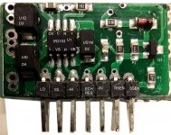
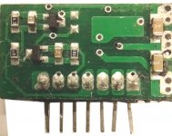
Here is the module depotted and a schematic thereof.
Pins 6 and 7 both come from the source current sense resistor. Thus Q3 is only turned on by the action of Q1 and Q2. The non stuffed resistor disables the, useful I would have thought, latching over current feature. To trip the current limit requires about 1.3V which equates to current of 4.5A if the sense resistor is 250m ohms. On my board the sense resistor was blown and it looks like the value was 25m ohms ( marked R025) making it essentially worthless.
My board blew both FETs, the sense resistor and the IR2153.
Attachments
500W PSU Module
Here is the module depotted and a schematic thereof. Pins 6 and 7 are both connected to the sense resistor.
The direct limit via Q3 is in effect disabled and so Q1 and Q2 are active. The latching feature is disabled by the non stuffed resistor.
Om my board the FET, the sense resistor and IR2153 were blown. The sense resistor looks like it was mark R025 which I think would be 25m ohms which seems rather low. 250m ohms would make more sense.
Attachments


Thank you nickbfl - my module was set in hard epoxy making it very difficult to dissect to reverse engineer - I had been looking for this schematic for some time now - by the way, the current sense resistor is 0.1 ohm 3W - I managed to trace the module and got the same schematic as you with minor capacitor differences - i built a through hole pcb using 2N5551 and 2N5401 devices. I used the IR2153D device, so omitted the flyback diode from pin 1 to pin 8 of the controller IC.
Here is the rest of the power supply in pdf format - I replaced the IRF740 fets with IRF460B devices (drilled extra holes to mount them) and found that i needed to increase the gate resistors to 33 ohms (I also placed reverse biased 1N4148 diodes in parallel with these gate resistors ) The rebuilt supply has been working well for a couple of years now - cheers bajaman
Here is the rest of the power supply in pdf format - I replaced the IRF740 fets with IRF460B devices (drilled extra holes to mount them) and found that i needed to increase the gate resistors to 33 ohms (I also placed reverse biased 1N4148 diodes in parallel with these gate resistors ) The rebuilt supply has been working well for a couple of years now - cheers bajaman