Having trouble finding any advice on derating transformers for use with voltage doublers/triplers.
Double the amount you would normally derate when using a standard rectification scheme for a doubler, triple for a tripler, etc has always been my rule of thumb. FWIW I don't tend to use much more than a doubler for anything other than very low power applications, as I like to use caps and diodes rated for the whole supply voltage that result from using the multiplier, just in case a part fails as a short or some other failure happens. Lower current needs less capacitance at higher voltages, so it's cheaper to buy lower F values at hgh voltage.
I typically don't use doublers at all these days, but have in the past. I tried to keep maximum output current to no more than 35% of the nominal current rating of the winding used. The advice in the previous comment is good and should put you in the same ballpark.
Being conservative costs a bit more money up front but may save you money in the long run if you don't have to replace the transformer.
Being conservative costs a bit more money up front but may save you money in the long run if you don't have to replace the transformer.
Doubler is same as capacitor input filter WRT transformer rating. Choke input filter - 100% rated VA, capacitor input 50%.
TANSTAAFL, as always, applies. Approx. 1/2 the AC RMS current is available as DC in a full wave rectified, cap. I/P filtered, PSU. A "full wave" doubler yields approx. 1/4 the RMS current as DC.
When correctly executed, a "full wave" doubler yields high performance. Correctly executed means spending some money on the items, like "hash" filters and chokes, that make performance high. Low copper losses are a potential virtue, of a "full wave" doubler.
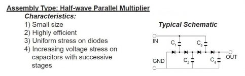
In the low to medium current situation, a 1/2 wave parallel multi-stage multiplier yields satisfactory results. Notice the increasing WVDC required of the caps., as the stage count grows.
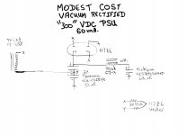
For S&Gs, I'm providing a low current vacuum rectified doubler PSU. The setup is just fine feeding a RCA phono stage, original or tweaked.
When correctly executed, a "full wave" doubler yields high performance. Correctly executed means spending some money on the items, like "hash" filters and chokes, that make performance high. Low copper losses are a potential virtue, of a "full wave" doubler.
In the low to medium current situation, a 1/2 wave parallel multi-stage multiplier yields satisfactory results. Notice the increasing WVDC required of the caps., as the stage count grows.
For S&Gs, I'm providing a low current vacuum rectified doubler PSU. The setup is just fine feeding a RCA phono stage, original or tweaked.
Attachments
Contrary to conventional wisdom, the difference between the two main types of doublers and ordinary rectifiers is relatively marginal: it is particularly true regarding the power factor.
Here is a fair comparison example (same hardware expense, etc.):
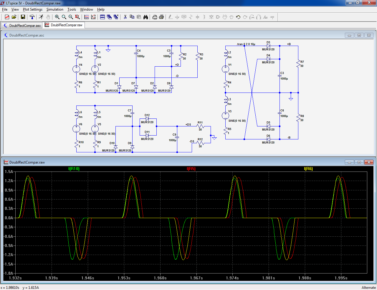
In fact, the counter-intuitive result is that, of the three, the Schenkel (capacitive) doubler is (marginally) the best: in this example, 494mA rms against 529mA rms for the two other.
How is this possible?
Because the DC output of the Schenkel is marginally lower. If the capacitors were increased to match the output of the two others, the rms current would also increase.
This means that there is a small penalty to be paid for doublers, especially the Schenkel type, but it is relatively insignificant when the tolerances of E-caps are factored-in
Here is a fair comparison example (same hardware expense, etc.):
In fact, the counter-intuitive result is that, of the three, the Schenkel (capacitive) doubler is (marginally) the best: in this example, 494mA rms against 529mA rms for the two other.
How is this possible?
Because the DC output of the Schenkel is marginally lower. If the capacitors were increased to match the output of the two others, the rms current would also increase.
This means that there is a small penalty to be paid for doublers, especially the Schenkel type, but it is relatively insignificant when the tolerances of E-caps are factored-in
Attachments
- Status
- Not open for further replies.
- Home
- Amplifiers
- Power Supplies
- Derating transformer for capacitive voltage doubler